Display assembly
This section describes removing the display assembly in its entirety and disassembling all the display
subcomponents.
If you only need to remove the display bezel, webcam/microphone module, or display panel, you do not need
to remove the entire display assembly from the computer. See
Display subcomponents (bezel, webcam,
panel) on page 39
for more information about removing the display subcomponents that do not require that
you remove the entire display assembly from the computer.
Description
Spare part number
Raw display panel
(39.6-cm [15.6-in], HD, WLED, BrightView)
For use in models without a touch screen
750635-001
For use in models with a touch screen
774167-001
Antennas
For use in models without a touch screen (includes wireless antenna cables and transceivers)
749638-001
For use in models with a touch screen (includes wireless antenna cables and transceivers)
774163-001
Display bezel
749644-001
Display cable
For use in non-touch screen models (includes display panel cable and webcam/microphone cable)
749646-001
For use in touch screen models (includes display panel cable and webcam/microphone cable)
764888-001
Display enclosure, touch screen models
Touch screen models
774164-001
Non-touch screen models
749641-001
Hinges (left and right)
Non-touch screen models
749655-001
Touch screen models
774166-001
Webcam/microphone module
749654-001
Before removing the display assembly, follow these steps:
1.
Shut down the computer. If you are unsure whether the computer is off or in Hibernation, turn the
computer on, and then shut it down through the operating system.
2.
Disconnect all external devices connected to the computer.
3.
Disconnect the power from the computer by first unplugging the power cord from the AC outlet and
then unplugging the AC adapter from the computer.
4.
Remove the battery (see
Battery on page 31
).
5.
Remove the following components:
●
Keyboard (see
Keyboard on page 35
)
●
Top cover (see
Top cover on page 43
)
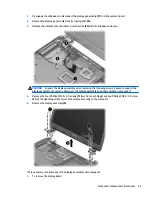
To remove the display assembly:
66
Chapter 6 Removal and replacement procedures for Authorized Service Provider parts
Содержание 255 G3
Страница 1: ...HP 255 G3 Notebook PC Maintenance and Service Guide ...
Страница 4: ...iv Safety warning notice ...
Страница 12: ...4 Chapter 1 Product description ...
Страница 34: ...26 Chapter 3 Illustrated parts catalog ...
Страница 46: ...38 Chapter 5 Removal and replacement procedures for Customer Self Repair parts ...
Страница 53: ...9 Remove the top cover 2 Reverse this procedure to install the top cover Component replacement procedures 45 ...
Страница 80: ...72 Chapter 6 Removal and replacement procedures for Authorized Service Provider parts ...
Страница 84: ...76 Chapter 7 Using Setup Utility BIOS and HP PC Hardware Diagnostics UEFI in Windows 8 1 ...
Страница 88: ...80 Chapter 8 Using Setup Utility BIOS and System Diagnostics in Windows 7 ...
Страница 114: ...106 Chapter 14 Statement of Volatility ...
Страница 118: ...110 Chapter 15 Power cord set requirements ...

