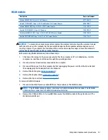
System board
NOTE:
The system board spare part kit includes replacement thermal materials.
Description
Spare part
number
System board
(includes processor):
All system boards use the following part numbers:
xxxxxx-001: Without the Windows operating system
xxxxxx-501: Windows 8.1 Standard
xxxxxx-601: Windows 8.1 Professional
For use in models with a touch screen:
●
AMD A8-6410 processor and UMA graphics memory
764000-xxx
●
AMD A6-5200 processor and UMA graphics memory
763021-xxx
For use in models without a touch screen:
●
AMD A8-6410 processor and UMA graphics memory
763999-xxx
●
AMD A4-6210 processor and UMA graphics memory
764001-xxx
●
AMD A4-6210 processor and 1 GB of discrete graphics memory
764004-xxx
●
AMD E2-6110 processor and UMA graphics memory
764002-xxx
●
AMD E1-6010 processor and UMA graphics memory
764003-xxx
●
AMD A6-5200 processor and UMA graphics memory
761533-xxx
●
AMD A4-5000 processor and 1 GB of discrete graphics memory
761534-xxx
●
AMD A4-5000 processor and UMA graphics memory
761532-xxx
●
AMD E2-3800 processor and UMA graphics memory
761530-xxx
●
AMD E1-2100 processor and UMA graphics memory
761531-xxx
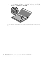
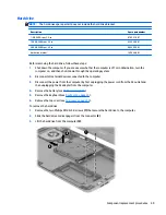
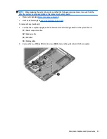
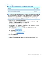
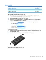
Before removing the system board, follow these steps:
1.
Shut down the computer. If you are unsure whether the computer is off or in Hibernation, turn the
computer on, and then shut it down through the operating system.
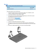
2.
Disconnect all external devices connected to the computer.
3.
Disconnect the power from the computer by first unplugging the power cord from the AC outlet and
then unplugging the AC adapter from the computer.
4.
Remove the battery (see
Battery on page 31
).
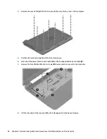
5.
Remove the following components:
●
Keyboard (see
Keyboard on page 35
)
●
Top cover (see
Top cover on page 43
)
●
WLAN module (see
WLAN module on page 51
)
●
Hard drive (see
Hard drive on page 49
)
56
Chapter 6 Removal and replacement procedures for Authorized Service Provider parts
Содержание 255 G3
Страница 1: ...HP 255 G3 Notebook PC Maintenance and Service Guide ...
Страница 4: ...iv Safety warning notice ...
Страница 12: ...4 Chapter 1 Product description ...
Страница 34: ...26 Chapter 3 Illustrated parts catalog ...
Страница 46: ...38 Chapter 5 Removal and replacement procedures for Customer Self Repair parts ...
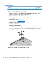
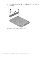
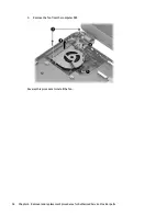
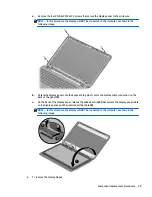
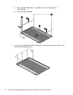
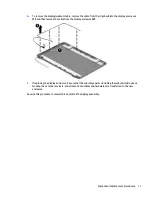
Страница 53: ...9 Remove the top cover 2 Reverse this procedure to install the top cover Component replacement procedures 45 ...
Страница 80: ...72 Chapter 6 Removal and replacement procedures for Authorized Service Provider parts ...
Страница 84: ...76 Chapter 7 Using Setup Utility BIOS and HP PC Hardware Diagnostics UEFI in Windows 8 1 ...
Страница 88: ...80 Chapter 8 Using Setup Utility BIOS and System Diagnostics in Windows 7 ...
Страница 114: ...106 Chapter 14 Statement of Volatility ...
Страница 118: ...110 Chapter 15 Power cord set requirements ...