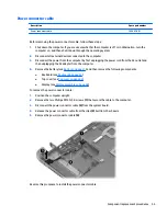


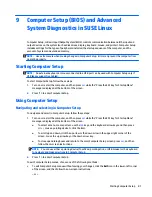

1.
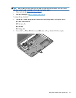
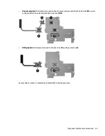
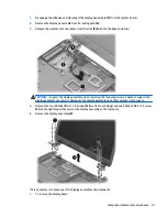
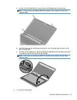
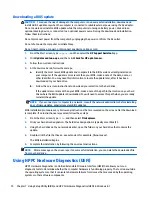
Disengage the adhesive and disconnect the display panel cable
(1)
from the system board.
2.
Remove the display panel cable from its routing path
(2)
.
3.
Release the wireless antenna cables from the clips
(3)
built into the base enclosure.
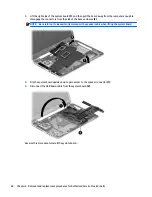
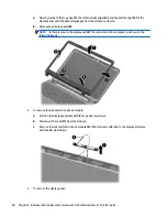
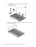
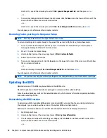
CAUTION:
Support the display assembly when removing the following screws. Failure to support the
display assembly can result in damage to the display assembly and other computer components.
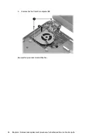
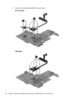
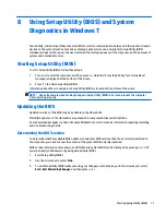
4.
Remove the four Phillips PM2.5×5.0 screws
(1)
(two from each hinge) and one Phillips PM2.5×3.5 screw
(2)
(on the right hinge) that secures the display assembly to the computer.
5.
Remove the display assembly
(3)
.
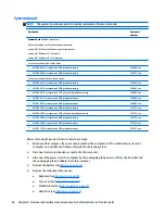
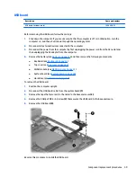
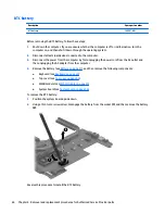
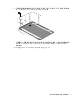
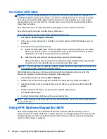
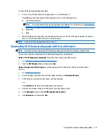
If it is necessary to replace any of the display assembly subcomponents:
1.
To remove the display bezel:
Component replacement procedures
67
Содержание 255 G3
Страница 1: ...HP 255 G3 Notebook PC Maintenance and Service Guide ...
Страница 4: ...iv Safety warning notice ...
Страница 12: ...4 Chapter 1 Product description ...
Страница 34: ...26 Chapter 3 Illustrated parts catalog ...
Страница 46: ...38 Chapter 5 Removal and replacement procedures for Customer Self Repair parts ...
Страница 53: ...9 Remove the top cover 2 Reverse this procedure to install the top cover Component replacement procedures 45 ...
Страница 80: ...72 Chapter 6 Removal and replacement procedures for Authorized Service Provider parts ...
Страница 84: ...76 Chapter 7 Using Setup Utility BIOS and HP PC Hardware Diagnostics UEFI in Windows 8 1 ...
Страница 88: ...80 Chapter 8 Using Setup Utility BIOS and System Diagnostics in Windows 7 ...
Страница 114: ...106 Chapter 14 Statement of Volatility ...
Страница 118: ...110 Chapter 15 Power cord set requirements ...