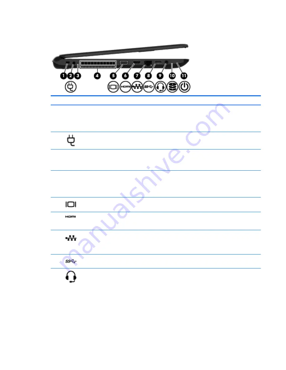
Left side
Component
Description
(1)
Security cable slot
Attaches an optional security cable to the computer.
NOTE:
The security cable is designed to act as a deterrent, but
it may not prevent the computer from being mishandled or
stolen.
(2)
Power connector
Connects an AC adapter.
(3)
AC adapter light
●
On: The AC adapter is connected and the battery is
charged.
●
Off: The computer is using battery power.
(4)
Vent
Enables airflow to cool internal components.
NOTE:
The computer fan starts up automatically to cool
internal components and prevent overheating. It is normal for
the internal fan to cycle on and off during routine operation.
(5)
External monitor port (select models only)
Connects an external VGA monitor or projector.
(6)
HDMI port
Connects an optional video or audio device, such as a high-
definition television, any compatible digital or audio
component, or a high-speed HDMI device.
(7)
RJ-45 (network) jack/status lights
Connects a network cable.
●
White: The network is connected.
●
Amber: Activity is occurring on the network.
(8)
USB 3.0 port
Connects an optional USB device, such as a keyboard, mouse,
external drive, printer, scanner or USB hub.
(9)
Audio-out (headphone)/Audio-in (microphone)
jack
Connects optional powered stereo speakers, headphones,
earbuds, a headset, or a television audio cable. Also connects an
optional headset microphone. This jack does not support
optional microphone-only devices.
WARNING!
To reduce the risk of personal injury, adjust the
volume before putting on headphones, earbuds, or a headset.
For additional safety information, refer to the
Regulatory,
Safety, and Environmental Notices
. To access this guide in
Windows 8.1, from the Start screen, type
support
, and then
select the
HP Support Assistant
app.
NOTE:
When a device is connected to the jack, the computer
speakers are disabled.
Left side
7
Содержание 255 G3
Страница 1: ...HP 255 G3 Notebook PC Maintenance and Service Guide ...
Страница 4: ...iv Safety warning notice ...
Страница 12: ...4 Chapter 1 Product description ...
Страница 34: ...26 Chapter 3 Illustrated parts catalog ...
Страница 46: ...38 Chapter 5 Removal and replacement procedures for Customer Self Repair parts ...
Страница 53: ...9 Remove the top cover 2 Reverse this procedure to install the top cover Component replacement procedures 45 ...
Страница 80: ...72 Chapter 6 Removal and replacement procedures for Authorized Service Provider parts ...
Страница 84: ...76 Chapter 7 Using Setup Utility BIOS and HP PC Hardware Diagnostics UEFI in Windows 8 1 ...
Страница 88: ...80 Chapter 8 Using Setup Utility BIOS and System Diagnostics in Windows 7 ...
Страница 114: ...106 Chapter 14 Statement of Volatility ...
Страница 118: ...110 Chapter 15 Power cord set requirements ...


