


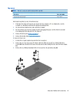
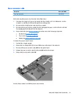
3.
Disconnect the power from the computer by first unplugging the power cord from the AC outlet and
then unplugging the AC adapter from the computer.
4.
Remove the battery (see
Battery on page 31
).
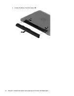
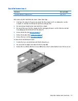
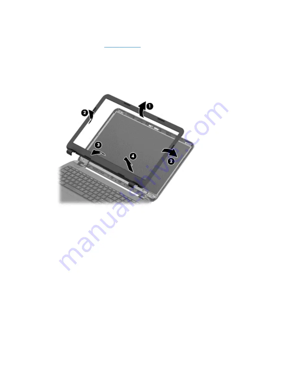
To remove the display bezel, webcam/microphone module, and raw display panel:
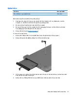
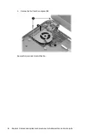
1.
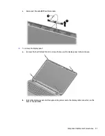
Position the computer upright with the front toward you, and then open it.
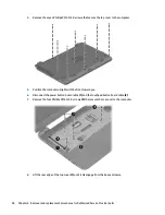
2.
Flex the inside of the top edge
(1)
, the left and right sides
(2)
, and the bottom edge
(3)
of the display
bezel until the bezel disengages from the display enclosure.
3.
Remove the display bezel
(4)
.
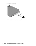
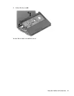
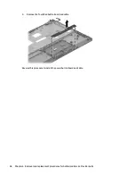
4.
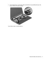
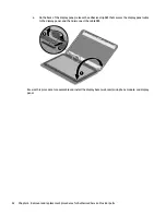
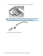
To remove the webcam/microphone module:
a.
Position the display assembly with the top edge toward you.
b.
Lift to disengage the adhesive that secures the webcam/microphone module to the display, and
then remove the module enough to access the cable connection on the module
(1)
.
40
Chapter 6 Removal and replacement procedures for Authorized Service Provider parts
Содержание 255 G3
Страница 1: ...HP 255 G3 Notebook PC Maintenance and Service Guide ...
Страница 4: ...iv Safety warning notice ...
Страница 12: ...4 Chapter 1 Product description ...
Страница 34: ...26 Chapter 3 Illustrated parts catalog ...
Страница 46: ...38 Chapter 5 Removal and replacement procedures for Customer Self Repair parts ...
Страница 53: ...9 Remove the top cover 2 Reverse this procedure to install the top cover Component replacement procedures 45 ...
Страница 80: ...72 Chapter 6 Removal and replacement procedures for Authorized Service Provider parts ...
Страница 84: ...76 Chapter 7 Using Setup Utility BIOS and HP PC Hardware Diagnostics UEFI in Windows 8 1 ...
Страница 88: ...80 Chapter 8 Using Setup Utility BIOS and System Diagnostics in Windows 7 ...
Страница 114: ...106 Chapter 14 Statement of Volatility ...
Страница 118: ...110 Chapter 15 Power cord set requirements ...


