Operating Instructions
Art.: 80730200 en
Read carefully prior to starting up!
Keep operating instructions in a safe place!
04/2007
Specialists in modern
cultivation and seeding technology
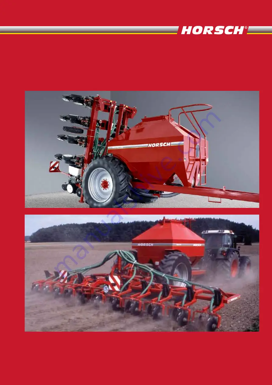
HORSCH Säwagen
HORSCH Säwagen
SW 3500 S / 7000 S
SW 3500 S / 7000 S


