C
OMMISSIONING
40 / 157
System 6844(RC) - V03.00
hopf
Elektronik GmbH
Nottebohmstr. 41
• D-58511 Lüdenscheid • Tel.: +49 (0)2351 9386-86 • Fax: +49 (0)2351 9386-93 • Internet: http://www.hopf.com • E-Mail: [email protected]
4
Commissioning
This chapter describes the commissioning of the system 6844(RC).
4.1
General Procedure
The commissioning procedure is as follows:
Check the cabling:
o
Earth
o
Power supply
o
Connection of the GPS Antenna System (GPS only)
and the appropriate synchronisation source for Sub-Master (Slave) Systems
o
GPS antenna equipment
o
COM0 / COM1 serial interfaces
o
DCF77 antenna simulation (77.5kHz)
o
Error relays (1U only)
o
Function Boards
Isolate all plug connections to the output interfaces and Function Boards (recom-
mended)
GPS antenna equipment connection to the Sync.-Source remain in place (e.g. GPS
antenna equipment, and so on)
Switch on System 6844(RC)
Power LEDs light up on front and rear sides (1U only)
The start frame appears on the display (for approx. 3 seconds)
Execute all parameter settings via the
SET menu
and also via the
INI
and
S.CLOCK menus
when necessary
Check for successful synchronization of the System 6844(RC)
Commission the Function Boards (where present):
o
Set the Function Board(s) parameters
o
Re-establish the plug connections
o
Check that the connected equipment is receiving the time correctly
4.2
Switching on the Operating Power Supply
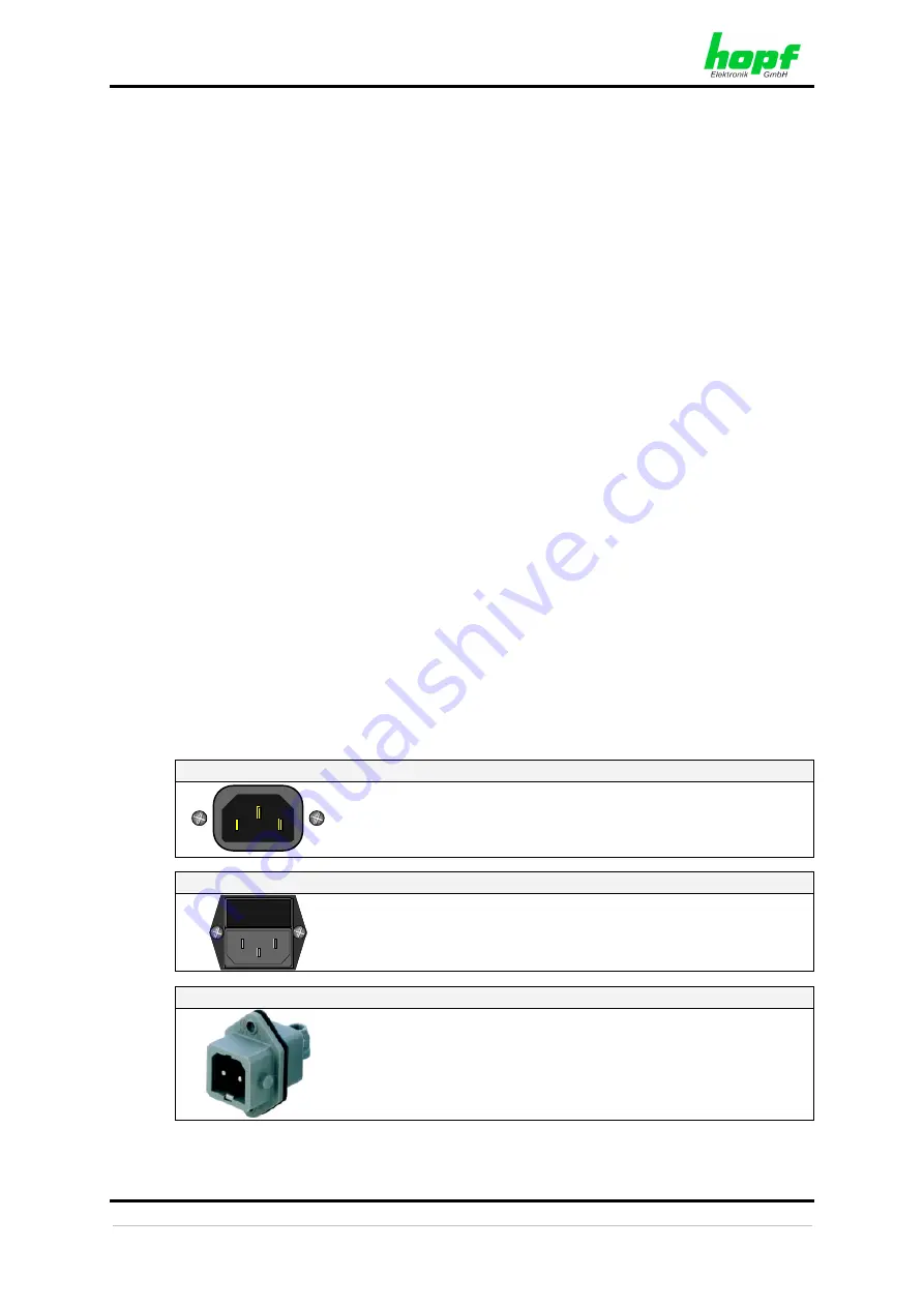
AC power supply 3U / Table-Top / Wall:
Switch on external power supply.
The System 6844(RC) runs and the firmware version and pro-
gramming date are shown on the display (see
Chapter 4.3 Dis-
play after System Start/Reset (Firmware)
AC power supply 1U:
I O
Put the mains power switch into position "
I
" (on).
The System 6844(RC) 1U Slim Line runs and the firmware version
and programming date are shown on the display
(see
Chapter 4.3 Display after System Start/Reset (Firmware)
DC power supply:
Switch on external power supply source.
The System 6844(RC) 1U Slim Line runs and the firmware version
and programming date are shown on the display
(see
Chapter 4.3 Display after System Start/Reset (Firmware)
The green Power LED resp. the power supply LED light up for both power supplies.


