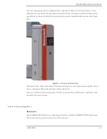
SCANNER SAFETY AND LOCAL CONTROLS
6510020335
48
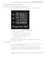
ash sensor will only light up when the shutter is open during scanning and standardize
(see Figure 47). The basis weight sensor nuclear source cannot be turned off but its
shutter action can be specifically disabled with user panel.
Fig. 47.
X-ray Power Enabled On User Panel
Purpose:
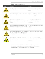
The red and green indicators on the user panel and heads indicate the shutter status of
radiation, X-ray or nuclear, sensors. They determine if sensor heads are safe to be
approached within the 1 m (3.28 ft) radiation hazard zone (see Table 8).
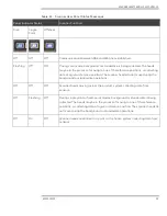
Table. 8.
Red Green Shutter Status Indicator Safety Summary
Indicator
Shutter Safety Condition
Green only
All microswitches activated by sensor shutters are in a safe closed position. It is
safe to work around the scanner head.
Red only
A command to open a shutter has been issued by the control system and a shutter
is open (green light off). Stay back 1m (3.28 ft) from heads.
Green and Red
A command to open a shutter has been issued, but the sensor shutter has not
physically opened for some reason. This is a safe condition but not a normal
operating mode. System may need repairs.
No Green or Red
The green light circuit has been opened by either a sensor shutter switch or
incorrect wiring. No shutter open command is active. This is not a normal operating
mode; assume that a radiation shutter may be stuck open, and troubleshoot
system.
The amber indicator ring around the ash sensor button (see Figure 2-48), indicates that
the X-ray source is in a powered condition.
The red indicator above the sensor buttons show shutter status, open (red) or closed (off).
The green light also provides an interlock control to ensure safe operation of the head split
mechanism. The head split command will be ignored if the green indicator is not on,
despite the amber light showing next to the head split switch.
Содержание Experion MX
Страница 1: ...Experion MX RELEASE 702 1 Operators Guide 6510020335 Rev 02 May 2019 ...
Страница 7: ...6510020335 7 8 NOTICES 168 ...
Страница 20: ...SCANNER SAFETY AND LOCAL CONTROLS 6510020335 20 Fig 15 Cable End Voltage Zones ...
Страница 21: ...SCANNER SAFETY AND LOCAL CONTROLS 6510020335 21 Fig 16 Distant End Voltage Zones ...
Страница 124: ...PROCESS INFORMATION DISPLAYS 6510020335 124 Fig 105 Profile Display ...
Страница 159: ...PROCESS INFORMATION DISPLAYS 6510020335 159 Fig 148 Precision Platform 4000 01 Scanner ...
Страница 160: ...PROCESS INFORMATION DISPLAYS 6510020335 160 Fig 149 Precision Platform 4000 20 21 Scanner ...


