SCANNER SAFETY AND LOCAL CONTROLS
6510020335
41
Purpose:
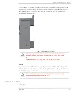
Crash switches are mounted in a groove in the upper track and are triggered just before
contact with the buffer stops at each end. Triggering a crash switch signals the frame
control system to stop the motor.
Motion limit switches are mounted inboard of crash switch locations in the lower track,
and are marked as forward limit switch (distant end), and reverse limit switch (cable end).
These switches indicate to the frame control system that the scanner is close to limits of
travel, and are used to allow the scanner to:
•
be at zero encoder position at startup
•
indicate to the motion controller that further motion in a direction past a limit
switch toward a crash switch is not allowed
2.3.2.4 Head Split Interlock
Description:
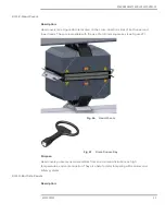
Magnetic reed switches mounted into the upper head alley are triggered by a magnet in
the lower head alley. The signal is armed when the heads are together, and is reported to
the upper head alley EDAQ PCB. Moving the heads apart breaks the interlock.
Purpose:
The head split interlock is checked by a number of scanner subsystems including:
•
Radiation (X-ray, nuclear, and laser) -based sensor software to ensure that the
opposing hardware is in place to capture potentially dangerous radiation beams
that would otherwise propagate in an unsafe manner
•
Frame control software to ensure that both heads are properly aligned prior to
scanning; might also indicate that a head or belt has become disconnected from
the drive system
2.3.2.5 Green Shutter Closed Indicator Interlock
Description:
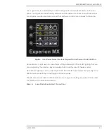
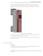
The green shutter closed indicator (see Figure 36) is driven by a simple hardwired (not
computer-based) circuit, serially routed through each green light and sensor location in
both upper and lower heads and user panels.
Fig. 36.
Green Shutter Closed Indicators
Содержание Experion MX
Страница 1: ...Experion MX RELEASE 702 1 Operators Guide 6510020335 Rev 02 May 2019 ...
Страница 7: ...6510020335 7 8 NOTICES 168 ...
Страница 20: ...SCANNER SAFETY AND LOCAL CONTROLS 6510020335 20 Fig 15 Cable End Voltage Zones ...
Страница 21: ...SCANNER SAFETY AND LOCAL CONTROLS 6510020335 21 Fig 16 Distant End Voltage Zones ...
Страница 124: ...PROCESS INFORMATION DISPLAYS 6510020335 124 Fig 105 Profile Display ...
Страница 159: ...PROCESS INFORMATION DISPLAYS 6510020335 159 Fig 148 Precision Platform 4000 01 Scanner ...
Страница 160: ...PROCESS INFORMATION DISPLAYS 6510020335 160 Fig 149 Precision Platform 4000 20 21 Scanner ...


