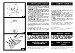
DISIMBALLO
6
Dopo aver tolto l'imballaggio assicurarsi dell'integrità della
macchina controllando che non vi siano parti visibilmente
danneggiate.
Gli elementi dell'imballaggio non devono essere lasciati alla
portata dei bambini in quanto potenziali fonti di pericolo.
N.B.: Conservare l'imballo per eventuali trasporti futuri.
INSTALLAZIONE
7
Scegliere il luogo di installazione osservando le norme vigenti sulla
sicurezza del lavoro. La pavimentazione dell'ambiente non deve
essere sconnessa in modo da poter rendere stabile la macchina
e consentire ai rulli della pedana di scorrere liberamente.
Se l'installazione viene eseguita in un luogo aperto è necessaria
la presenza di una tettoia per la protezione dalla pioggia .
Le condizioni ambientali di lavoro devono essere conformi ai
seguenti requisiti:
- umidità relativa da 30% a 95% senza condensa;
- temperatura da 0° a 55° C.
6
Once the packing material has been removed, check the
machine visually for any signs of damage.
Keep the packing materials out of the reach of children as they
can be a source of danger.
N.B.: Keep the packing for possible future transport.
7
INSTALLATION
Choose the place the machine is to be installed in compliance
with current work place safety regulations. The floor should not
be broken or uneven so that the machine will be stable and
the platform rollers can move freely.
If the installation is outdoor, it must be protected by some kind
of roofing against rain.
The following work environment conditions are applicable:
Relative humidity: from 30-95% without condensation;
Temperature: from 0-55° C.
UNPACKING
B/5
A
7.1
7.1
INSTALLATION PLACE
LUOGO DI INSTALLAZIONE
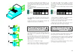
2500 mm
2500 mm
1000 mm
700 mm
ATTENZIONE!
Non è consentito l'utilizzo della macchina
in atmosfera esplosiva.
ATTENTION!
The machine must not be operated in
explosive atmospheres.
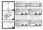
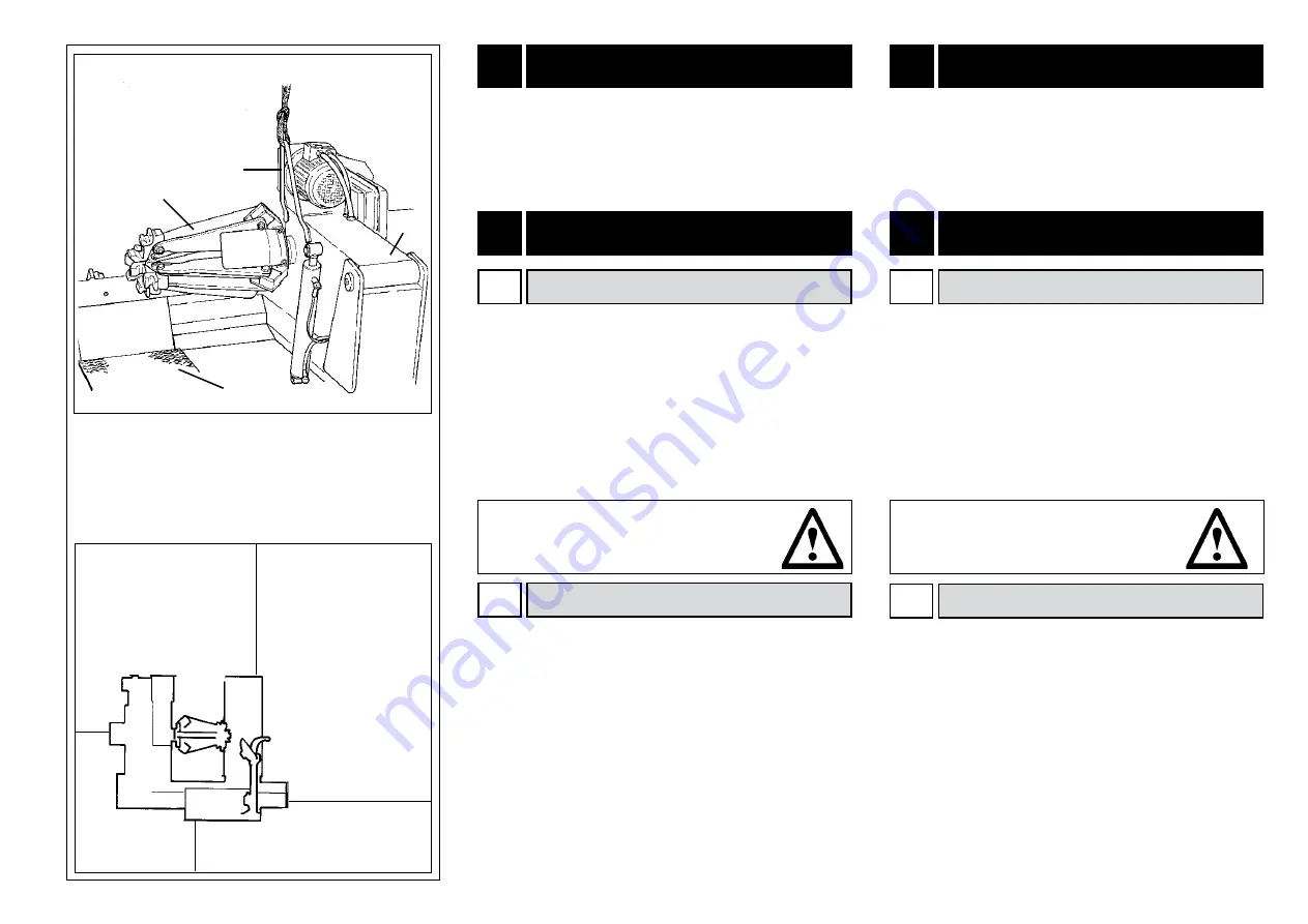
L'area di ingombro massima della macchina è di mm. 2240 x
1640, mantenendo una distanza minima da eventuali pareti
come indicato in Fig. B/5.
ATTENZIONE.: Queste dimensioni indicano anche l'area opera-
tiva dello smontagomme. Deve essere fatto assoluto divieto
a qualsiasi persona, che non sia personale opportunamente
addestrato ed autorizzato, di entrare in tale area.
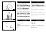
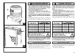
Posizionare lo Smontagomme utilizzando, come punto di
sollevamento, l'apposita staffa (1, fig A) con il braccio porta-
autocentrante (2, fig. A) completamente abbassato, l'auto
-
centrante (3, fig. A) chiuso, il carrello porta-utensile (4, fig. A) a
fine corsa, vicino al braccio.
La colonnetta mobile di comando non deve avere una
posizione predefinita, ma deve essere posizionata in modo
Maximum machine space requirements are 2240x 1640 mm with
a minimum distance from walls as shown in the diagram.
CAUTION! These measurements are also the tyre changers work-
ing range. Persons other than specially trained and authorized
operators are expressly forbidden to enter this area.
Position the tyre changer lifting it with the specific bracket (1,
Fig. A) with the tool carrier arm (2, Fig. A) lowered all the way,
the spindle (3, Fig. A) closed and the tool carrier slide (4, Fig.
A) at its stop close to the arm.
The mobile control unit has no fixed position, but it must be
positioned in a way that the user can observe the machine
when working
7.2
POSIZIONAMENTO
7.2
1
3
2
WORKPLACE REQUIREMENT
Содержание MEGAMOUNT 551
Страница 62: ...62 SCHEMA ELETTRICO ELECTRIC DIAGRAM SCHEMA ELECTRIQUE SCHALTPLAN ESQUEMA ELECTRICO 110 V 1 ph ...
Страница 63: ...63 SCHEMA ELETTRICO ELECTRIC DIAGRAM SCHEMA ELECTRIQUE SCHALTPLAN ESQUEMA ELECTRICO 230 V 1 ph ...
Страница 64: ...64 SCHEMA ELETTRICO ELECTRIC DIAGRAM SCHEMA ELECTRIQUE SCHALTPLAN ESQUEMA ELECTRICO 220 V 3 ph ...
Страница 65: ...65 SCHEMA ELETTRICO ELECTRIC DIAGRAM SCHEMA ELECTRIQUE SCHALTPLAN ESQUEMA ELECTRICO 400 V 3 ph ...
Страница 66: ...66 SCHEMA ELETTRICO ELECTRIC DIAGRAM SCHEMA ELECTRIQUE SCHALTPLAN ESQUEMA ELECTRICO ...
Страница 67: ...67 ...
Страница 68: ...68 SCHEMA IDRAULICO HYDRAULIC DIAGRAM SCHEMA HYDRAULIQUE HYDRAULIKPLAN ESQUEMA HIDRAULICO ...


