3
P
13.3
RUOTE CON CAMERA D'ARIA
STALLONATURA
13.3
TUBED WHEELS
BEAD BREAKING
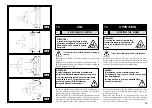
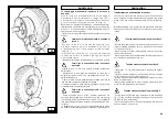
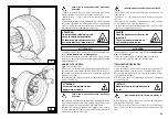
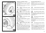
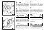
WARNING: Unscrew the bush which fixes the valve when deflat
-
ing the tyre so that the valve, coming in the inside of the rim, is
not an obstacle during bead breaking.
Follow all the steps described previously for bead breaking
tubeless tyres.
With tubed tyres, however, stop disk movement as soon as
the bead has loosened to avoid damaging the tube inflation
ATTENZIONE: Quando si sgonfia la ruota è necessario svitare
la ghiera che fissa la valvola in modo che, quest'ultima, rien-
trando all'interno del cerchio, non costituisca ostacolo durante
la stallonatura.
Procedere alle operazioni di stallonatura agendo esattamente
come descritto per le ruote Tubeless.
Nel caso di ruote con camera d'aria è però necessario interrom-
pere l'avanzamento del disco stallonatore immediatamente
dopo il distacco del tallone per evitare possibili danni a valvola
1)
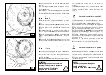
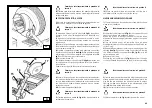
Ribaltare il braccio porta utensile
(14, Fig. D)
in posizione di
fuori lavoro, traslarlo sul lato esterno della ruota e riagganciarlo
in posizione di lavoro.
2)
Ruotare l'autocentrante e contemporaneamente fare avan-
zare l'utensile a becco
(18, Fig. D)
inserendolo tra cerchio e
tallone fino a che quest'ultimo si sarà agganciato all'utensile.
3)
Allontanare di circa 4-5 cm. il cerchio dall'utensile in modo
da evitare l'eventuale sgangio del tallone dall'utensile stesso.
4)
Traslare verso l'esterno l'utensile a becco in modo da
portare il suo punto rosso di riferimento in prossimità del bordo
esterno del cerchio.
SMONTAGGIO
DEMOUNTING
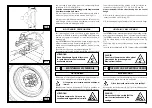
Take the mobile control unit to work position C.
Portarsi con la colonnetta mobile in posizione di
lavoro C.
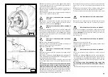
1)
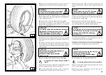
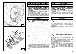
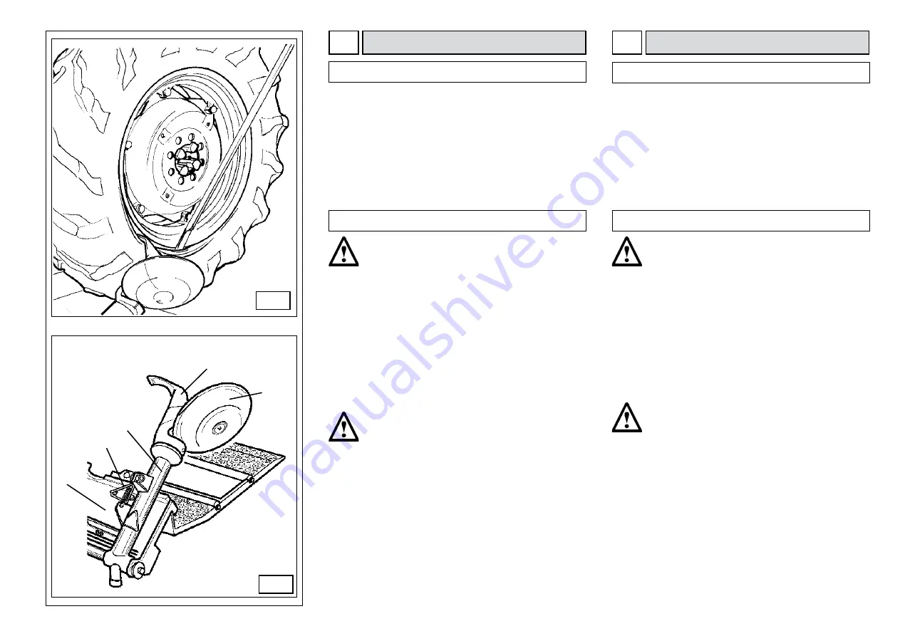
Tip the tool carrier arm
(14, Fig. D)
to its non-working posi-
tion. Move it to the outside plane of the wheel and rehook it
in this position.
2)
Rotate the wheel and at the same time move the hook tool
(18, Fig. D)
forward inserting it between rim and bead until it is
anchored to the tool.
3)
Move the rim 4-5 cm from the tool taking care that it does
not unhook from the bead.
4)
Move the hook tool towards the outside until the red refer-
ence dot is by the outside edge of the rim.
Portarsi con la colonnetta mobile in posizione
di lavoro B.
5)
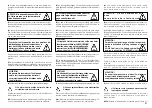
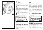
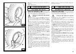
Insert lever
(see Fig. P) between rim and bead at the right
of the tool.
6)
Press down on the lever and lower the wheel to bring the
edge of the rim about 5 mm from the hooked tool.
7)
Turn the wheel anticlockwise pressing down on lever
until
the bead is completely off.
8)
Move the tool carrier arm to its non-working position. Lower
the spindle until the tyre is pressed down against the platform
. As the platform is moved slightly towards the outside, the tyre
will open a little and thus create enough space to remove the
inner tube.
D
Take the mobile control unit to work position B.
5)
Inserire la leva
(vedi Fig. P) tra cerchio e tallone sulla destra
dell'utensile.
6)
Mantenendo la leva premuta abbassare la ruota fino a
portare il bordo del cerchio ad una distanza di circa 5 mm.
dall'utensile a becco.
7)
Girare la ruota in senso antiorario mantenendo premuta la
leva
fino alla completa fuoriuscita del tallone.
8)
Allontanare il braccio porta utensile in posizione di fuori
lavoro. Abbassare l'autocentrante fino a premere la gomma
sulla pedana mobile che, avanzata leggermente verso l'ester-
no, creerà lo spazio necessario per l'estrazione della camera
d'aria.
1
13
1
1
1
Содержание MEGAMOUNT 551
Страница 62: ...62 SCHEMA ELETTRICO ELECTRIC DIAGRAM SCHEMA ELECTRIQUE SCHALTPLAN ESQUEMA ELECTRICO 110 V 1 ph ...
Страница 63: ...63 SCHEMA ELETTRICO ELECTRIC DIAGRAM SCHEMA ELECTRIQUE SCHALTPLAN ESQUEMA ELECTRICO 230 V 1 ph ...
Страница 64: ...64 SCHEMA ELETTRICO ELECTRIC DIAGRAM SCHEMA ELECTRIQUE SCHALTPLAN ESQUEMA ELECTRICO 220 V 3 ph ...
Страница 65: ...65 SCHEMA ELETTRICO ELECTRIC DIAGRAM SCHEMA ELECTRIQUE SCHALTPLAN ESQUEMA ELECTRICO 400 V 3 ph ...
Страница 66: ...66 SCHEMA ELETTRICO ELECTRIC DIAGRAM SCHEMA ELECTRIQUE SCHALTPLAN ESQUEMA ELECTRICO ...
Страница 67: ...67 ...
Страница 68: ...68 SCHEMA IDRAULICO HYDRAULIC DIAGRAM SCHEMA HYDRAULIQUE HYDRAULIKPLAN ESQUEMA HIDRAULICO ...

