2
SMONTAGGIO
DEMOUNTING
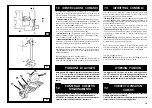
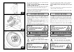
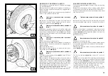
Tubeless tyres can be demounted in two ways:
1)
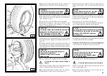
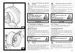
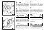
If the tyre is not difficult to demount, once the beads have
been loosened, use the bead disk to push against the inside
plane of the tyre until both beads come off the rim (See Fig.
H).
2)
With Supersingle or very hard tyres the procedure described
above cannot be used. The hook tool will have to be used as
follows:
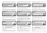
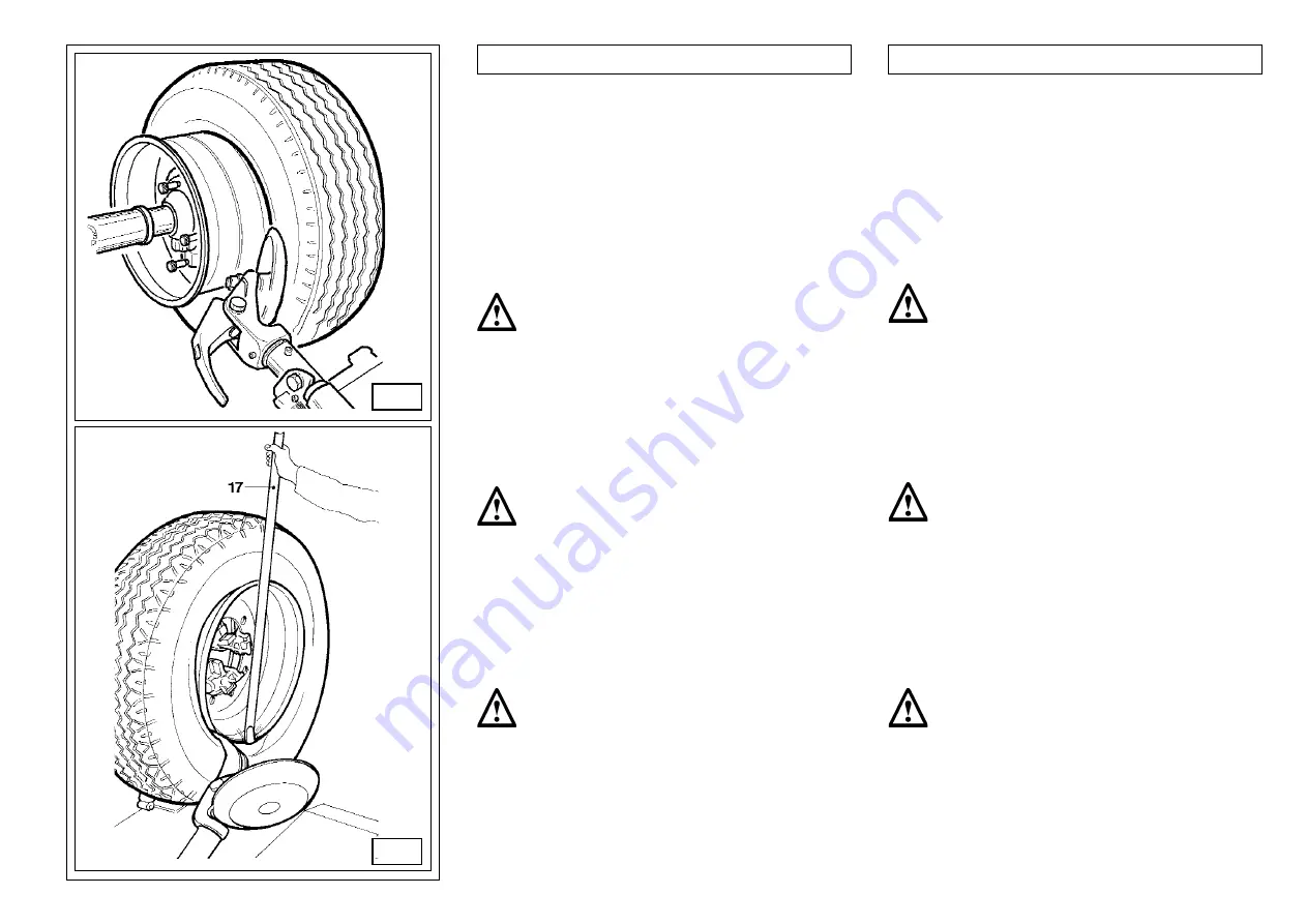
- Inserire la leva (17, Fig. I) tra cerchio e tallone sulla destra
dell'utensile.
- Mantenendo la leva premuta abbassare la ruota fino a
portare il bordo del cerchio ad una distanza di circa 5 mm.
dall'utensile a becco.
- Girare la ruota in senso antiorario mantenendo premuta la
leva fino alla completa fuoriuscita del tallone.
- Allontanare il braccio porta utensile in posizione di fuori lavoro
e traslarlo sul lato interno della ruota.
- Girare l'utensile a becco di 180°, inserire il medesimo tra
cerchio e tallone (vedi fig.L) e traslarlo fino a che il tallone sia
in prossimità del bordo anteriore del cerchio ( é consigliabile
fare quest'ultima operazione ruotando contemporaneamente
la ruota).
- Allontanare di circa 4-5 cm. il cerchio dall'utensile in modo
da evitare l'eventuale sgangio del tallone dall' utensile stesso.
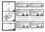
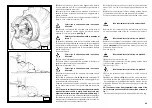
- Insert lever
(17, Fig. I) between rim and bead at the right of
the tool.
-Press down on the lever and lower the wheel to bring the edge
of the rim about 5 cm from the hooked tool.
-Turn the wheel anticlockwise pressing down on lever
until the
bead is completely off.
-Move the tool carrier arm to its non-working position and then
move it to the inside plane of the wheel.
Lo smontaggio di pneumatici tubeless può avvenire in
due modi:
1)
Se la ruota non presenta difficoltà di smontaggio
proseguire, dopo la stallonatura, spingendo con il
disco stallontore sul fianco interno del pneumatico fino
a far uscire i due talloni dal cerchio (vedi fig. H).
2)
Se la ruota è del tipo SUPERSINGLE, o comunque è partico-
larmente dura e pertanto non è possibile agire come descritto
al punto 1, si rende necessario l'utilizzo dell'utensile a becco
operando nel modo seguente:
- Traslare il braccio portautensile sul fianco esterno del pneu
-
matico.
- R u o t a r e l a r u o t a e c o n t e m p o r a n e a m e n t e f a r e
avanzare l'utensile a becco inserendolo tra cerchio
e tallone finchè non si sia ancorato al tallone stesso
(vedi Fig. I).
-Allontanare di circa 4-5 cm. il cerchio dall'utensile
in modo da evitare l'eventuale sgangio del tallone
dall'utensile stesso.
-Translare verso l'esterno l'utensile a becco in modo da portare
I
Portarsi con la colonnetta mobile in posizione
di lavoro B.
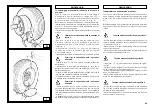
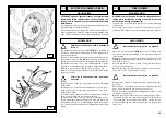
- Rotate the wheel and at the same time move the hook tool
forward inserting it between rim and bead until it is anchored
to the bead (See Fig. I).
-Move the rim 4-5 cm from the tool taking care that it does not
unhook from the bead.
-Move the hook tool towards the outside until the red reference
dot is by the outside edge of the rim.
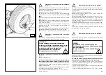
-Turn the hook tool 180° and insert it between rim and bead (see
Fig. L). Move it until the bead is by the edge of the rim (best to
do this with the wheel turning).
-Move the rim about 4-5 cm from the tool making sure the hook
does not detach from the rim.
H
Portarsi con la colonnetta mobile in posizione
di lavoro D.
Portarsi con la colonnetta mobile in posizione di
lavoro C.
Take the mobile control unit to work position C.
Take the mobile control unit to position B.
Take the mobile control unit to work position D.
Содержание MEGAMOUNT 551
Страница 62: ...62 SCHEMA ELETTRICO ELECTRIC DIAGRAM SCHEMA ELECTRIQUE SCHALTPLAN ESQUEMA ELECTRICO 110 V 1 ph ...
Страница 63: ...63 SCHEMA ELETTRICO ELECTRIC DIAGRAM SCHEMA ELECTRIQUE SCHALTPLAN ESQUEMA ELECTRICO 230 V 1 ph ...
Страница 64: ...64 SCHEMA ELETTRICO ELECTRIC DIAGRAM SCHEMA ELECTRIQUE SCHALTPLAN ESQUEMA ELECTRICO 220 V 3 ph ...
Страница 65: ...65 SCHEMA ELETTRICO ELECTRIC DIAGRAM SCHEMA ELECTRIQUE SCHALTPLAN ESQUEMA ELECTRICO 400 V 3 ph ...
Страница 66: ...66 SCHEMA ELETTRICO ELECTRIC DIAGRAM SCHEMA ELECTRIQUE SCHALTPLAN ESQUEMA ELECTRICO ...
Страница 67: ...67 ...
Страница 68: ...68 SCHEMA IDRAULICO HYDRAULIC DIAGRAM SCHEMA HYDRAULIQUE HYDRAULIKPLAN ESQUEMA HIDRAULICO ...


