2-19
Chapter 2
Installation and Wiring
2.11 Control circuit wiring section
■
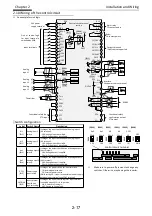
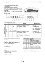
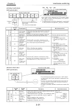
Input terminals
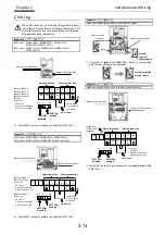
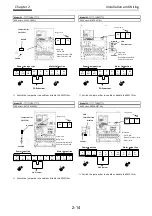
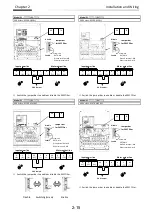
• All COMs have the same electric potential.
• Change SW5 to external power source (EX) to connect
the power source between Input terminals 1 to 9, A or
B, and COM.
• Sink or source logic of the input terminal is switched by
SW6.
(Wiring example)
• [] it means factory default settings.
■
Terminal’s default function ([symbol: setting No.])
[RS:028]Reset
• Reset at every trip.
[SCHG:015]Command source change
• Change to the main speed command [AA101](OFF) or
sub-speed command[AA102](ON).
[JG:029]Jogging
• Run at a frequency of [AG-20] upon receipt of the operation
command by [JG]ON.
[FRS:032]Free-run stop
• [FRS]ON sets the motor in a free-run state.
[2CH:031]Two-step acceleration/deceleration
• [2CH]ON enables acceleration/deceleration
time-2[AC124][AC126].
[EXT:033]External trip
•
[EXT]ON issues Trip[Er012].
[FW:001]Forward rotation and [RV:002]Reverse rotation
Forward
Reverse
Description
OFF
OFF
No command
ON
OFF
Forward rotation command operation
OFF
ON
Reverse rotation command operation
ON
ON
No command (inconsistent logic)
[CF1:003]Multispeed-1 and [CF2:004]Multispeed-2 commands
Multispeed-1
CF1
Multispee
d-2 CF2
Description
OFF
OFF
The set frequency source is enabled.
ON
OFF
The frequency source of [Ab-11] is enabled.
OFF
ON
The frequency source of [Ab-12] is enabled.
ON
ON
The frequency source of [Ab-13] is enabled.
*) Setting CF3 and 4 allows you to set up to 16-speed.
[USP:034]Unattended start protection
•
In a [USP]ON state, if an operation command has been input
before the power supply is ON, Trip[Er013] is issued.
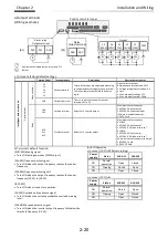
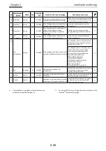
Terminal
label
Terminal
name
Description
Electric characteristics
In
te
ll
ig
e
n
t
in
p
u
t
te
rm
in
a
l
D
ig
it
a
l
in
p
u
t
C
o
n
ta
ct
9, 8,
7, 6,
5, 4,
3, 2,
1
Input
terminal
Terminal functions are selectable according to the
parameter settings for each terminal.
Switching SW6 to SRC or SINK allows you to select SINK or
Source logic.
Voltage between each input and
COM terminals
• ON voltage Min.DC18V
• OFF voltage Max.DC3V
• Max. allowable voltage DC27V
• Load current 5.6mA(at DC27V)
P
u
ls
e
A
Pulse input-A
This is a terminal for pulse input. A and B terminals can be
used also as an input terminal.
Terminal functions are selectable according to the
parameter settings for each terminal.
The maximum input pulse rate is 32kpps.
Voltage between an input and
COM terminals
• ON voltage Min.DC18V
• OFF voltage Max.DC3V
• Max. allowable voltage DC27V
• Load current 5.6mA(at DC27V)
• Max input pulse rate 32kpps
B
Pulse input-B
C
o
m
m
o
n
COM
Input
(common)
This is a common terminal for digital input terminals
(1,2,3,4,5,6,7,8,9,A and B). Three COM terminals are
available.
Control circuit terminal
SW6
SW5
Input terminal
1
[RS]
2
[SCHG]
3
[JG]
4
[FRS]
5
[2CH]
6
[CF1]
7
[CF2]
8
[RV]
9
[FW]
A
[EXT]
B
[USP]
COM
COM
COM
Содержание P1-00041HFEF
Страница 6: ...0 5 Contents Contents Memo ...
Страница 42: ...2 26 Chapter 2 Installation and Wiring Memo ...
Страница 129: ...Index Index 3 memo ...
Страница 130: ...Index Index 4 memo ...

