Chapter 6 Communication Mode
6 - 48
Mod
b
u
s M
a
ster
Function code 0x10 (Force Multiple Registers)
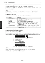
Function code 10 is a query to change two or more holding registers of slave. In broadcasting, the state of the same
holding registers of all slaves is changed.
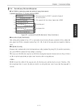
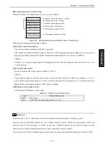
(1) Sending data area format
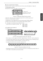
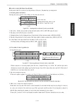
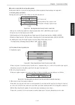
Sending data area changes with the number of the holding registers to change. Please set the head word to the
number of transmission bytes.
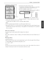
Figure 6.47 Sending data area format (Function code 0x10)
1) Device No.: Set the slave number by hexadecimal number. (H01 to HFF. H00 is for broadcast.)
2) Function code: Set the function code to H10.
3) Starting address: Set the starting address of holding register to change by hexadecimal number.
(H0000 to HFFFF)
4) Number of holding registers: Set the number of holding registers to change by hexadecimal number.
(H0000 to H007F)
5) Value of holding registers: Set the value of the holding registers to change.
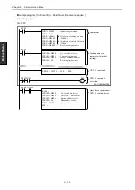
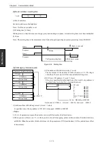
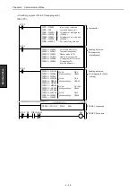
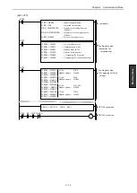
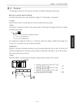
Ex.) Change the values of holding registers 40101 and 40102 of slave No.90 to H1234 and H5678:
The head address of Sending data area WR100
WR100 = H000A
WR101 = H5A10
WR102 = H0064
WR104 = H0002
WR105 = H1234
WR106 = H5678
(2) The state of receiving data area
1) Completed properly
When performance is properly, completion flag (t+1) will be ON, and nothing is stored in receiving data area. A
properly execution code is stored in a return code (s+0).
2) Receiving exception response
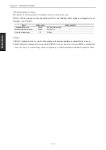
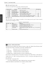
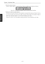
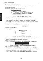
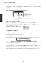
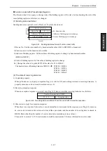
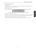
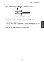
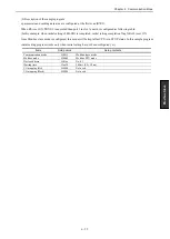
When an exception response is received, error flag (t+2) turns on, and the receiving data area is as follows.
Figure 6.48 Receiving data area format (Function code 0x10 / Exception response)
3) Other errors (except for exception response)
When there is no response from a slave or an abnormal factor is detected in the response, error flag (t+2) turns on,
an error code is stored in the return code area of the s parameter, and the number of receiving data is cleared to
H0000. (Data other than the number of receive data bytes maintains previous values.)
Please refer to section “6.3.5 Error detection in modbus master mode” for more information on error codes.
Exception code
Number of receive data (H0002)
H 9 0
1 word
Number of send data (bytes)
Holding register1
Device No.
1 0
Starting address
…
Holding register n
Number of registers
10: Function code
Starting address of holding register to control
The number of holding registers to change
Value of the holding registers to change
Содержание EH-150 Series
Страница 1: ...HITACHI PROGRAMMABLE CONTROLLER Serial Communication Module EH SIO APPLICATION MANUAL NJI 443F X ...
Страница 2: ......
Страница 10: ...M E M O ...
Страница 30: ...Chapter 4 Installation 4 10 M E M O ...
Страница 156: ...Chapter 7 System setup 7 12 M E M O ...
Страница 164: ...Chapter 8 Daily and Periodic Inspection 8 8 M E M O ...

