Chapter 4 Installation
4 - 7
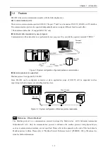
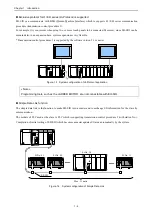
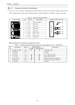
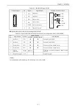
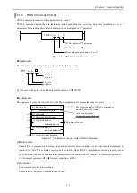
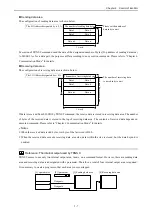
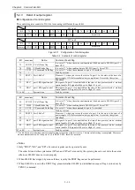
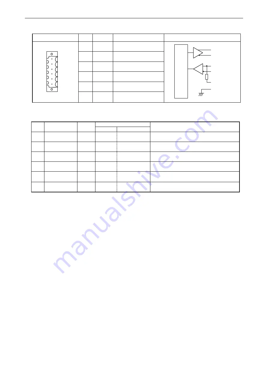
Table 4.8 RS-422/485 Signal (Port2)
Terminal layout
No.
Signal
Signal Name
Diagram of internal circuit
6
1
. .
.
.
1
SD +
Send data +
M
icro
P
ro
ce
ss
o
r
6) SG
1) SD+
2) SD–
3) RD+
4) RD–
5) TERM
+
–
+
–
110
2
SD –
Send data –
3
RD +
Receive data +
4
RD –
Receive data –
5
TERM
Built-in terminator
6
SG
Ground for signal
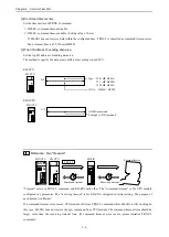
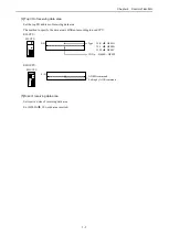
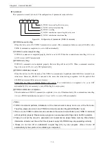
Signal name and Connector pin arrangement (Port2)
Table 4.9 Signal name (EH-SIO side) and connector pin arrangement (Port2 / RS-422/485)
Pin
No.
Signal Name
Symbol
Signal Direction
Specifications
EH-SIO
External device
1
Send data +
SD +
Data send from EH-SIO.
2
Send data –
SD –
Data send from EH-SIO.
3
Receive data +
RD +
Data received from external device.
4
Receive data –
RD –
Data received from external device.
5
Built-in
terminator
TERM
(
RD –)
--
When you use built-in terminator, please connect
with RD –.
6
Ground for signal
SG
--
--
Ground for signal
« Note »
A communication cable should use the twisted pair wire with a shield.
Содержание EH-150 Series
Страница 1: ...HITACHI PROGRAMMABLE CONTROLLER Serial Communication Module EH SIO APPLICATION MANUAL NJI 443F X ...
Страница 2: ......
Страница 10: ...M E M O ...
Страница 30: ...Chapter 4 Installation 4 10 M E M O ...
Страница 156: ...Chapter 7 System setup 7 12 M E M O ...
Страница 164: ...Chapter 8 Daily and Periodic Inspection 8 8 M E M O ...

