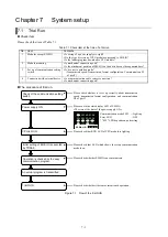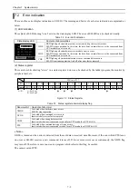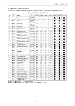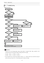
Chapter 6 Communication mode
6 - 96
S
imp
le
d
at
a l
ink
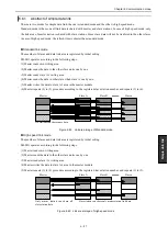
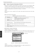
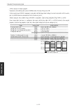
Execution of Initial setting
Set command execution request bit (t+0) ON after storing required data to both s parameter and sending data area.
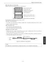
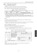
Completion of Initial setting
(1) Completed properly
H0000 is stored return code area (s+0) and completion bit (t+1) is turned ON. XIC2 and TII2 of status register are
turned ON, LNK of status LED is turned ON and MB2, HP2 and MS2 of status LEDs are turned OFF.
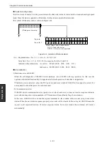
(2) Error
Error bit (t+2) is turned ON and error code which indicates a cause is stored into return code area.
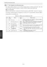
Refer to the return code of “6.6.6 Error detection in simple data link mode” and remove the cause of each error.
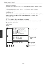
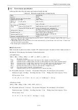
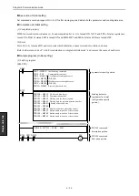
Sample program [ Initial setting ]
(1) Ladder program
[EH-CPU]
TRNS 9 ( WY215 , WR0 , M0 )
WR7 = H0000
Initial setting command
WR8 = 200
Command timeout time
WR9 = H000A
I/O address of sending data area
WRA = H0100
( WR100 )
WRB = H000A
I/O address of receiving data area
WRC = H0200
( WR200 )
WRD = H0002
Receiving data area size
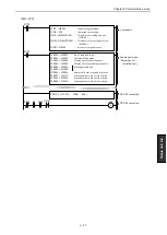
WR100 = H0012
No. of send data (byte)
WR101 = H0030
Communication mode
WR102 = H0002
Waiting time for slave response
WR103 = H0002
Waiting time for switching station number
WR104 = H000A
Setting of data link area
WR105 = H1000
WR106 = H0016
Number of words occupied by master
WR107 = H0132
Station number, words of slave station
WR108 = H0208
Station number, words of slave station
WR109 = H0324
Station number, words of slave station
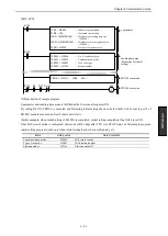
S
R7E3
R7E3
M0
R7E3
s parameter specify portion
Sending data area
(parameter for initial
configuration specify
portion)
TRNS 9 command
description portion
TRNS 9 command
Execution portion
DIF1 X2129
Содержание EH-150 Series
Страница 1: ...HITACHI PROGRAMMABLE CONTROLLER Serial Communication Module EH SIO APPLICATION MANUAL NJI 443F X ...
Страница 2: ......
Страница 10: ...M E M O ...
Страница 30: ...Chapter 4 Installation 4 10 M E M O ...
Страница 156: ...Chapter 7 System setup 7 12 M E M O ...
Страница 164: ...Chapter 8 Daily and Periodic Inspection 8 8 M E M O ...

