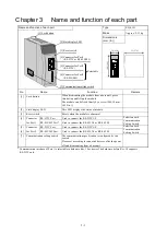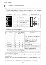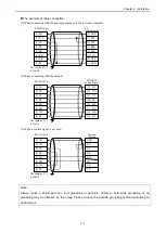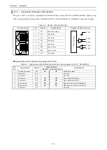
Chapter 3 Name and function of each part
3 - 2
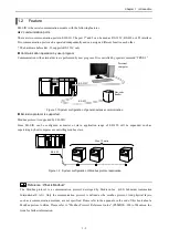
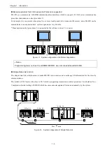
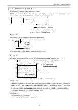
Display of LED
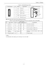
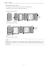
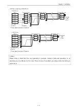
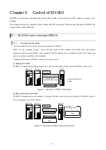
Table 3.1 Contents of LED display
Appearance
LED
Contents of display
Details
Color
Hard Rev. 04 or before
SERIAL I/O
EH-SIO
MDE CDE
SD2 RD2
WDE
MB1 HP1 MB2 HP2
MS1
MS2 422
LNK
SD1 RD1
Hard Rev. 10 or newer
SERIAL I/O
EH-SIO
MDE CDE
SD2 RD2
WDE
MB1 HP1 MB2 HP2
MS1 422
1
MS2 422
2
LNK
SD1 RD1
LNK
Simple Data Link Mode
*1
Lighting when the simple data link mode setting
Green
WDE
Watchdog Timer Error
Lighting when MPU error (Serious failure)
Port 1, Port 2 combined use
Red
MDE
Module Error
Lighting when module error (Serious failure)
Port 1, Port 2 combined use
Red
CDE
Command Error
Lighting when the command error and so on
(Minor failure) Port 1, Port 2 combined use
Red
SD1
Send Data
Flickering when sending data (Port1)
Green
RD1
Receive Data
Flickering when receiving data (Port1)
Green
MB1
During Modbus Mode
Lighting on Modbus mode setting (Port1)
Green
HP1
During Hi-Protocol
Mode
*1
Lighting on Hi-Protocol mode setting (Port1)
Green
MS1
During Modbus Master
Mode
Lighting on Modbus Master mode setting (Port1)
Green
422
1
Select RS-422 / 485 I/F
*2
Lighting when select the RS-422 / 485 I/F (Port1)
Green
SD2
Send Data
Flickering when sending data (Port2)
Green
RD2
Receive Data
Flickering when receiving data (Port2)
Green
MB2
During Modbus Mode
Lighting on Modbus mode setting (Port2)
Green
HP2
During Hi-Protocol
Mode
*1
Lighting on Hi-Protocol mode setting (Port2)
Green
MS2
During Modbus Master
Mode
Lighting on Modbus Master mode setting (Port2)
Green
422
2
Select RS-422 / 485 I/F
*2
Lighting when select the RS-422 / 485 I/F (Port2)
Green
*1 “Hi-Protocol” and “Simple data link” mode are supported by software ver. 2.0 or newer.
*2 Added / Changed from hardware Rev. 10.
When power supply turned on, state display LED except ERR, RD, SD are turned on. ("422
1
", "422
2
" are turned on or
off according to the state of a communication setting switch.) By executing initial setting, LED other than the set-up
communication mode turned off.
Please refer to "Chapter 7 System setup" about error LED (WDE, MDE, CDE).
Содержание EH-150 Series
Страница 1: ...HITACHI PROGRAMMABLE CONTROLLER Serial Communication Module EH SIO APPLICATION MANUAL NJI 443F X ...
Страница 2: ......
Страница 10: ...M E M O ...
Страница 30: ...Chapter 4 Installation 4 10 M E M O ...
Страница 156: ...Chapter 7 System setup 7 12 M E M O ...
Страница 164: ...Chapter 8 Daily and Periodic Inspection 8 8 M E M O ...


