Chapter 6 Communication mode
6 - 82
Hi
-P
ro
to
col
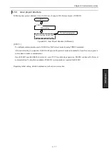
Execution of Initial setting
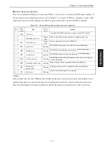
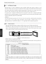
Set command execution request bit (t+0) ON after storing required data to both s parameter and sending data area.
« Note »
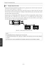
The maximum number of EH-SIO modules specified as Hi-Protocol mode is 8 with one CPU module.
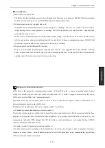
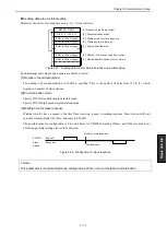
Completion of initial setting
(1) Completed properly
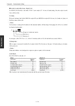
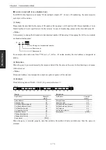
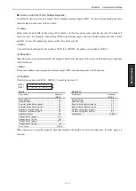
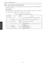
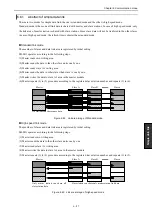
H0000 is stored return code area (s+0) and completion bit (t+1) is turned ON. XICx and TIIx of status register are
turned ON, HPx of status LEDis turned ON and LNK, MBx and MSx of status LEDs are turned OFF.
(x-1 : port 1, x-2 : port2)
(2) Error
Error bit (t+2) is turned ON and error code is stored into return code area.
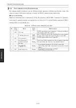
Please remove the cause of error by reference to the return code in “6.5.5 Error detection in Hi-Protocol mode”.
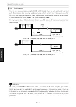
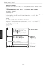
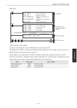
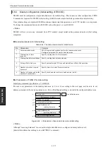
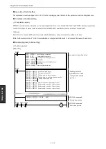
Sample program [ initial setting ]
(1) Ladder program
[EH-CPU]
TRNS 9 ( WYA5 , WR0 , M0 )
WR7 = H0000
Initial configuration command
WR8 = 200
Command timeout time
WR9 = H000A
I/O address of sending data area
WRA = H0100
( WR100 )
WRB = H000A
I/O address of receiving data area
WRC = H0200
( WR200 )
WRD = H0002
Receiving data area size
WR100 = H0006
No. of send data
WR101 = H0020
Communication mode
WR102 = H0001
Task code type
WR103 = H2700
Station number
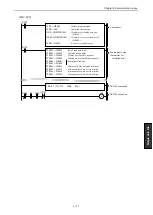
S
R0 DIF1
R7E3
R7E3
M0
R7E3
s parameter specify portion
Sending data area
(parameter for initial
configuration specify
portion)
TRNS 9 command
description portion
TRNS 9 command
execution portion
XA29
Содержание EH-150 Series
Страница 1: ...HITACHI PROGRAMMABLE CONTROLLER Serial Communication Module EH SIO APPLICATION MANUAL NJI 443F X ...
Страница 2: ......
Страница 10: ...M E M O ...
Страница 30: ...Chapter 4 Installation 4 10 M E M O ...
Страница 156: ...Chapter 7 System setup 7 12 M E M O ...
Страница 164: ...Chapter 8 Daily and Periodic Inspection 8 8 M E M O ...

