Chapter 6 Communication Mode
6 - 32
Mod
b
u
s M
a
ster
Sending data area for initial setting
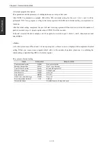
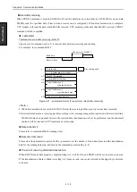
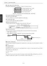
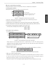
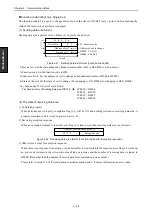
Sending data area (head address is specified as s+9 and s+A) format is as follows:
Figure 6.25 Sending data area format (Modbus master / Initial setting)
The meaning of each parameter described as below.
[1] Number of send data (bytes)
Set 6 byte (H0006) in case of modbus master mode (initial setting).
[2] Communication mode
In case of modbus master mode, please set to H0010.
[3] Modbus transmission mode
Modbus transmission mode is specified as either ASCII mode or RTU mode.
Table 6.9 Modbus transmission mode
Setting value
Transmission mode
H0000
RTU mode
Others
ASCII mode (Not supported in software ver. 1.0)
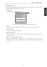
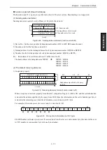
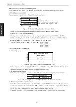
[4] Receiving timeout time
Receiving timeout is defined as time between the end of query and the end of received response.
H0000
Timeout disabled.
H0000
Timeout enabled in setting time x 10ms. The maximum timeout is HFFFF.
Figure 6.26 Monitoring of receiving timeout
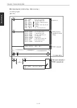
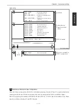
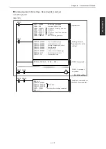
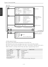
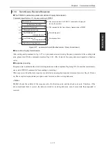
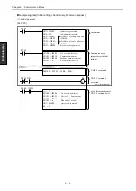
Execution of initial setting
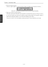
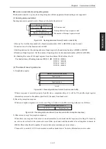
After the required s parameter and parameter for sending data are stored, please turn on the command execution
flag (t+0).
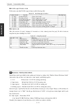
End of initial setting
(1) Completed properly
H0000 is stored in return code area (s+0), and completion flag (t+1) goes on. A status register XICx goes on and
LNK and HPx on the LED will be off.
(x-1: Port 1, 2: Port 2)
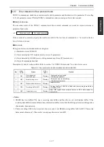
(2) Error
Error flag (t+2) goes on, and error code will be stored in return code area. Please eliminate the error factor by
referring to the return code in section “6.3.5 Error detection in modbus master mode”.
Response
Timeout
Query
Receiving timeout error
[1] Number of send data (bytes) [Fixed]
[4] Receiving timeout time
[2] Modbus master mode [Fixed]
[3] Modbus transmission mode
H 0 0 0 6
H 0 0 1 0
(Refer to below)
(Refer to below)
Содержание EH-150 Series
Страница 1: ...HITACHI PROGRAMMABLE CONTROLLER Serial Communication Module EH SIO APPLICATION MANUAL NJI 443F X ...
Страница 2: ......
Страница 10: ...M E M O ...
Страница 30: ...Chapter 4 Installation 4 10 M E M O ...
Страница 156: ...Chapter 7 System setup 7 12 M E M O ...
Страница 164: ...Chapter 8 Daily and Periodic Inspection 8 8 M E M O ...

