background image

53

_____________________________________________________________________________________________

8.1 Detail Printing

______________________________________________________________________________________________

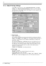
3. Time-axis Zoom

Selecting [

Same as Screen

] prints data using the same time axis

magnification as that of the chart shown on the screen. Any data exceeding
one page will be printed on multiple pages.
[

Fit to One Page

] automatically reduces the time axis magnification so that

the data is printed on one page only.
Selecting [

Each 1DIV

] for the "

Page Break

" setting causes the printer to end a

page at every division. Selecting [

Each 5DIV

] causes the printer to end a

page at every five divisions. These options cannot be selected when [

Fit to

One Page

] is selected.

4. Specify margins/Set 1DIV to 1cm

[

Specify Margin

] allows you to specify the left, right, top, and bottom

margins in units of 1 mm. The chart size will be reduced according to the
margins set.
[

Set 1DIV to 1cm

] prints the data with a grid set to 1 cm. With some printers,

all data may not be printed.
Printing with a grid of 1 cm is only available for printing on A4 and A3
paper. When printing on other size of paper, choose [

Specify Margin

].

5. Margins

Set the left, right, top, and bottom margins in increments of 1 mm.

6. Sheet

Set the sheet to print. Choose [

All

] or [

Only Displayed

].

7. Grid type

Select a type of grid from [

OFF

], [

Standard

], [

Detail

], and [

Time-axis

].

8. Gage

Select a type of gage from [

Upper / Lower

] and [

Detail

]. [

Upper / Lower

]

prints the upper and lower limit values of each channel only. [

Detail

] prints

the upper and lower limit values and the values on all scale graduations. One
gage is printed for every channel. Therefore, print areas for waveforms will
be reduced when there are many channels.
[

Max

] sets the maximum number of detail gages to print per chart. If there

are more channels than the maximum number set, the gages will be printed
for channels with higher display priority. Note that some printing formats
may provide fewer gages than specified in this setting.

9. Channel Marker

Set a print method for the channel markers of analog and logic waveforms.
Choose [

OFF

], [

CH Number.

], or [

Comment

]. Selecting [

Comment

] without

setting a comment for a channel will only print the CH No. for that channel.

10. Header

Specify the information you want to include in the header. Select
"

Measurement Info.

", "

Info.+Title Comment

", or "

Info.+File Name.

"

11. CH Info.

Set whether to print channel information (e.g., range and display
magnification). Choose [OFF] or [ON].

Содержание 9334

Страница 1: ...Instruction Manual For は専用機種 複数の場合は で区切る 不要の場合はとる 形名を入力 複数の場合は で区切る 9334 品名を入力 LOGGER COMMUNICATOR December 2014 Revised edition 3 9334A981 03 14 12H ...

Страница 2: ......

Страница 3: ...1 2 Setting IP Address of MEMORY HiLOGGER Used for Data Acquisition 14 4 1 3 Settings of MEMORY HiLOGGERs 15 4 1 4 Settings of Measurement Channels and Modules 17 4 1 5 Saving a Setting File 18 4 2 Starting Aborting Real Time Data Acquisition 19 4 2 1 Starting Real Time Data Acquisition 19 4 2 2 Aborting Real Time Data Acquisition 20 4 3 Screens During Real Time Data Acquisition 20 4 3 1 Waveform ...

Страница 4: ...5 5 1 Event Marker Search Function 33 5 5 2 Other Search Functions 34 5 6 Other Display Modifications 36 5 6 1 Changing the Origin and Magnification of Displayed Waveforms 36 5 6 2 Including Comments 36 5 6 3 Inserting Event Markers 37 5 6 4 Displaying Waveform Legends 37 5 6 5 Setting the Legend Channel Format 38 5 6 6 Turning the Channel Marker On and Off 38 5 6 7 Split Screen Settings 39 5 6 8 ...

Страница 5: ...gging Printing 57 8 3 1 Logging Printing 57 8 3 2 Logging View Print Preview 57 8 3 3 Logging Print Settings 58 Chapter 9 Logger Monitoring 59 9 1 Startup 59 9 2 Monitoring Settings 60 9 2 1 New Logger Registration 60 9 2 2 Changing Monitoring Settings 61 9 2 3 Deleting a Registered Logger 61 9 3 General Settings 61 9 4 Control 62 9 4 1 Starting Ending Monitoring 62 9 4 2 Starting Aborting Measure...

Страница 6: ......

Страница 7: ..._____________________________________________________________________________________________ ______________________________________________________________________________________________ ...

Страница 8: ..._____________________________________________________________________________________________ ______________________________________________________________________________________________ ...

Страница 9: ...er touch the recorded side of the disc Do not place the disc directly on anything hard Do not wet the disc with volatile alcohol or water as there is a possibility of the label printing disappearing To write on the disc label surface use a spirit based felt pen Do not use a ball point pen or hard tipped pen because there is a danger of scratching the surface and corrupting the data Do not use adhe...

Страница 10: ...ii _____________________________________________________________________________________________ ______________________________________________________________________________________________ ...

Страница 11: ...from up to 16 MEMORY HiLOGGERs When you are acquiring data in addition to waveforms you can also confirm values and alarms in real time 2 Various search functions In addition to event markers you can search for a variety of items including dates and maximum values 3 Waveform display Using a MEMORY HiLOGGER you can display waveform files saved to a PC card on the screen Binary data can also be save...

Страница 12: ...nels up to 256 logic channels and up to 64 pulse input channels Cursor function Allows you to display the time difference and potential difference between cursors A and B as well as the time and electrical potential at each cursor s position Parameter calculation function can select section or cursor interval Allows you to calculate the average peak maximum and minimum measurements as well as the ...

Страница 13: ...4 requires the following minimum hardware and software configuration Computer IBM PC AT compatible Pentium 133 MHz Pentium 200 MHz or more recommended 64 MB RAM 256 MB RAM recommended 5 MB of free hard disk space Operating system Microsoft Windows XP Windows Vista Windows 7 or Windows 8 Internet Explorer 4 01 or later LAN Physical LAN installation Communication using TCP IP CD ROM drive Used for i...

Страница 14: ... supplied CD R disc into the CD ROM drive 3 Run the setup file on the CD R Click Run on the Start menu then type R 9334ENGLISH setup exe and click OK Substitute the appropriate letter for R if your CD ROM drive uses a different name 4 The 9334 installer starts follow the directions on the screen to complete the installation 5 If Internet Explorer 4 01 or later is not installed install it For the l...

Страница 15: ...ace is required when using a PC card 2 Insert the supplied CD R disc into the CD ROM drive 3 Copy the upgrade file from the CD R to the PC card The upgrade files are located in each model s folder The upgrade file for the 8420 01 and 8421 01 is 8420V110 PRG located in the 8420V110 folder The upgrade file for the 8422 01 is 8422V105 PRG located in the 8422V105 folder The upgrade file for the 8420 5...

Страница 16: ...will need to obtain the following from your network administrator Host name This is the name of the MEMORY HiLOGGER on the network It must be distinct from the host names of all other devices on the network IP address This is the identifying address of the MEMORY HiLOGGER It must be distinct from the addresses of all other devices on the network Subnet mask This specifies the class size of the net...

Страница 17: ...e connected the last number should be incremented by one for each instrument for example the next instrument would be 192 168 0 3 The Host Name should be carefully selected to be unique among the Host Names assigned to all the other devices Otherwise the following settings should be satisfactory Subnet Mask 255 255 255 0 Default Gateway OFF Port Number 880X MEMORY HiLOGGER Settings Carry out the M...

Страница 18: ...____________________________________________________________________________________________ 2 4 LAN Settings ______________________________________________________________________________________________ ...

Страница 19: ... bar Toolbar Status Bar Chapter 3 Startup 3 1 Starting and Closing the Logger Communicator To start the Logger Communicator first click the Start menu button then point successively to Programs HIOKI 9334 Logger Communicator and finally click Logger Communicator To close the logger communicator on the File menu click Exit You can also click the Close button on the upper right corner of the window ...

Страница 20: ..._____________________________________________________________________________ 3 1 Starting and Closing the Logger Communicator ______________________________________________________________________________________________ ...

Страница 21: ...P addresses of MEMORY HiLOGGERs used for data acquisition These settings are made in the Measurement Settings dialog box On the menu click Measurement then click Settings to display the Measurement Settings dialog box The icons for Measurement 1 to Measurement 8 appear in the left box of the Measurement Settings dialog box These icons represent the eight measurement systems Up to 16 MEMORY HiLOGGE...

Страница 22: ...Click the Browse button to display the Browse dialog box and choose the folder there Setting Recording Interval Select a recording interval from the following presets 100 ms 200 ms 500 ms 1 s 2 s 5 s 10 s 20 s 30 s 1 min 2 min 5 min 10 min 20 min 30 min and 1 hr Setting Split Screen Select the number of split screens from the following presets 1 2 4 8 and 16 Setting Recording Period There are two ...

Страница 23: ...Axis Title You can set a title that is displayed on the time axis of a waveform graphic Setting Automatic Update Click Refresh button to display Auto Refresh Setting dialog box Check Auto Refresh during real time suspension and set the updating interval The waveform display will be updated when the set time elapses during real time suspension Check Auto change waveform sheet while measuring and se...

Страница 24: ... box to display the Settings page of the measurement system Click the Register button to display the IP Address Settings dialog box Type in the IP address of the MEMORY HiLOGGER to be used for data acquisition then click the Register button The MEMORY HiLOGGER is then registered for the measurement system and the logger icon appears under the measurement system icon For details on the settings of ...

Страница 25: ... To change the IP address or port number of a MEMORY HiLOGGER click the button The Change dialog box will then appear Type in a new address or port number For the port number use the number set on the MEMORY HiLOGGER with the low order digit changed to 0 For instance when 880X is set on the MEMORY HiLOGGER change the X to 0 and use 8800 instead Obtaining Logger Information After registering a MEMO...

Страница 26: ... internally calculated recording interval Sending Settings Send the settings made on the 9334 to the MEMORY HiLOGGER Click the Send Settings button to display the Send Settings dialog box Check the settings you want to send then click the Send button The settings will then be sent to the MEMORY HiLOGGER Receiving Settings Obtain the settings from the MEMORY HiLOGGER to the 9334 Click the Receive S...

Страница 27: ...er logic alarm and printer icons will then appear under the logger icon Note that the logic alarm and printer icons will not appear unless the 8992 PRINTER UNIT and 8993 DIGITAL I O UNIT are connected to the MEMORY HiLOGGER Double click an icon e g analog or pulse icon or click the plus mark to display the channel icons Click the channel trigger logic alarm or printer icon to display the related S...

Страница 28: ...rting Real Time Data Acquisition You can save the settings made in the Measurement Settings dialog box as a file Click the Save as button to display the Save As dialog box Choose a location at which to save the file type in the filename then click the Save button The Init button initializes all settings made in the Measurement Settings dialog box The Open file button is used to open an existing se...

Страница 29: ...he measurement system you want to use to start data acquisition Data acquisition will then begin After starting data acquisition the 9334 checks the settings of MEMORY HiLOGGERs registered for the measurement system for matching with those of the 9334 If the settings of any MEMORY HiLOGGER differ from those of the 9334 the Confirm dialog box will appear You can choose the settings of the 9334 or t...

Страница 30: ...pension you can scroll the screen to view the previous waveforms Clicking the button again during real time suspension will cause the viewer to start updating the waveforms again Even when the updating of waveforms is interrupted the 9334 continues acquiring and saving data in a file Click and drag the top of the status bar of the waveform viewer upward to display the information screen This scree...

Страница 31: ...isplayed each time you click the button To change the contents of the display on the View menu point to Unit then click Analog Pulse or Logic and change the contents of the display to Analog Pulse or Logic You can also click the toolbar buttons shown on the left Starting from the left Analog Display Pulse Display and Logic Display are shown 1 Displays the channel as a comment If no comment is set ...

Страница 32: ...nel Display On the View menu point to CH Comment then click Comment or CH You can also click the toolbar buttons shown on the left Starting from the left Comment Display and Channel Display are shown Changing the Display Update Interval You can select from 3 display update intervals 2 seconds 10 seconds and Hold To select a display update interval on the View menu point to Interval then click 2 Se...

Страница 33: ...click the toolbar button shown on the left From the left Large Display Small Display and Detailed Display are shown 1 Displays the current alarm output status in color When an alarm is output it displays red and when no alarm is output it displays green 2 Displays the current alarm output status in numerical values When an alarm is output 1 is displayed and when no alarm is output 0 is displayed 3...

Страница 34: ...be displayed Light mode settings If light mode is set to On you can easily confirm alarms visually because the entire background of the Alarm viewer lights red when an alarm is output for any channel To activate the light mode function on the View menu click Lighting You can also click the toolbar button shown on the left Changing Font On the View menu click Font to display the dialog box for font...

Страница 35: ...played Choose the file you want to open and click the Open button The file will be read into the 9334 and the waveform displayed Each HLW file stores the conditions under which a waveform is displayed on the waveform viewer For a MEM file a waveform setting file with extension HLC is created with the same filename as that of the MEM file and the display conditions are saved in this file The HLC fi...

Страница 36: ...ated when performing real time data acquisition The display conditions applied are only those that can be edited in the Measurement Settings dialog box On the View menu click Zoom In or Zoom Out The time axis is magnified or reduced You can also click either of the two toolbar buttons shown on the left Starting from the left Reduce Display and Magnify Display are shown You can also right click any...

Страница 37: ... the color and font of the characters of the time axis scale To do this right click near the time axis scale click Text Color or Font and the Settings dialog box appears You can change the magnification of the voltage axis To magnify the axis click Voltage Axis Magnification on the View menu You can also click the toolbar button shown on the left then click anywhere inside the waveform viewer Each...

Страница 38: ...box You can also make to activate and deactivate the gage for each channels in the Information screen To display the Information screen at the bottom of the screen click Information Screen on the Screen menu You can also click the toolbar button shown on the left For example when you click the Waveform button on the left of the Information screen you can activate or deactivate the gages of the cor...

Страница 39: ... 4 Using Cursors You can use cursors A and B to display cursor positions dates times and various types of cursor interval calculation results Click the toolbar buttons shown on the left then move the mouse pointer in the waveform viewer so it appears as a black arrow Click the desired position to set the cursor and an A mark or B mark appears at the top of the waveform viewer If you click the butt...

Страница 40: ...ag the edge of the Waveform Display screen or Cursor screen left or right to change the size of the Cursor screen 1 Click this to copy the display values to the clipboard text format You can then paste them into another program 2 Displays the position of the cursor on the time axis 3 Displays the alarm output of the cursor position Green No alarm Red One or more of the alarms are assigned to the c...

Страница 41: ...ursor on the Waveform Display screen Calculates the interval between the start measurement and cursor B Do not display the cursors on the Waveform Display screen Calculates all ranges 3 After data is acquired click to calculate 4 Click to copy the calculation results to the clipboard text format You can paste them into another program 5 Click to calculate in real time Calculations are done automat...

Страница 42: ...otal time during which the measurement value is higher than the set threshold value of the set calculation range Cannot be calculated for pulse OFF Time The total time during which the measurement value is lower than the set threshold value of the set calculation range Cannot be calculated for pulse ON Count The number of times that the measurement value rose above the set threshold value of the s...

Страница 43: ...that position to display the waveform First display the Information screen refer to 5 3 2 Changing the Gage Type To display the Event Search screen click Event Mark on the left of the Information screen 1 Click here to search for an event marker Click the event marker that you are searching for in the event marker list 2 Click here to delete event markers Click the event marker that you want to de...

Страница 44: ...screen to the right is searched for points that fulfill the search criteria that you have set and if any points are found the screen jumps to that point and displays the relevant waveform 3 Selects a search mode You can select from the following 9 search modes TIME AXIS Jumps to the set date Max Pos Jumps to the maximum measurement value of the channel being searched Min Pos Jumps to the minimum m...

Страница 45: ...Data Acquisition Copy the display value to the clipboard 2 Select the contents to be displayed 3 1 4 Sets items such as channels and search criteria The figure shows how to search for the maximum measurement If the Cursor screen is displayed you can display the date of the search point and the measurements for each channel 1 Displays the point that was searched 2 Displays the measurements of each ...

Страница 46: ...ens appear Click the channel number that you want to modify then set the origin magnification and scaling After you have entered the various values press the Enter key to apply the settings To learn more about scaling refer to the MEMORY HiLOGGER Operating Instructions Screen range Sets the upper and lower edge values on the Waveform screen If you scroll vertically using the vertical scroll bar on...

Страница 47: ...omment set the insert comment range then type the comment If you click the button on the toolbar once more the logger communicator exits this mode You can use the event marker function to attach event markers to acquired data either during or after acquisition for later recall refer to 5 5 Search Functions Click the toolbar button shown on the left then move the mouse pointer into the Waveform Vie...

Страница 48: ... the input type and the range On the View menu point to Channel Notation click Comment Channel or Setting then make the settings You can also click the toolbar buttons shown on the left Starting from the left Comment Channel and Settings are shown You can also right click anywhere inside the legend display frame point to Channel Notation then click Comment Channel or Setting Similarly to change th...

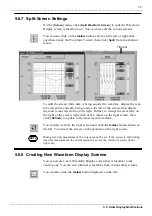
Страница 49: ... click on the toolbar button shown on the left or right click anywhere inside the Waveform Viewer then click Split from the shortcut menu To split the screen while data is being acquired in real time display the real time waveform currently being read on the left of the screen then display the most recent waveform on the right Further to change the waveform on the right of the screen right click n...

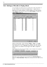
Страница 50: ...annels or 32 logic channels Click Screen on the menu bar then click Sheet Settings to display the Sheet Settings dialog box Choose a sheet tab S1 S16 click the Analog Pulse or Logic button then check the channels you want to display on the sheet When using an HLW file select a MEMORY HiLOGGER in the drop down list M1 to M16 to set channels for each logger Click OK to apply the settings Click a she...

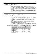
Страница 51: ... splits from 1 to 16 Screens The waveform display screen will be split horizontally into the selected number of charts The channels to display which charts are set on the Display Settings page of the information screen You can confirm waveform information for files that are currently open or being loaded and a variety of information for analog pulse logic and alarm settings First display the Infor...

Страница 52: ..._____________________________________________________________________________________ 5 6 Other Display Modifications ______________________________________________________________________________________________ ...

Страница 53: ..._________________________________________________________________________________ Chapter 6 Operating The Logging Viewer 6 1 Displaying the Logging Viewer When a waveform file has been read into the 9334 and the waveform viewer is displayed clicking Screen on the menu bar and choosing Logging View displays the logging view of the waveform file ...

Страница 54: ...Display Pulse Display Logic Display and Alarm Display are shown For Logic Display High status is displayed as 1 and Low status as 0 For Alarm Display 1 is displayed when an alarm is active and 0 is displayed when no alarm is active Also for Alarm Display Sheet 1 S1 is displayed as the first MEMORY HiLOGGER and Sheet 2 S2 as the second MEMORY HiLOGGER Changing the Channel Display You can select fro...

Страница 55: ...left Absolute Time Relative Time Seconds and Sampling Number are shown Tracing Settings during measurement When the tracing function is active you can update the display so that the time elapsed follows the values If this function is inactive the display is not updated until the data is completely loaded even if values are displayed all the way to the bottom of the display screen To activate or de...

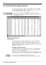
Страница 56: ...____________________________________________________________________________________ 6 2 Numerical Value Display Screen ______________________________________________________________________________________________ ...

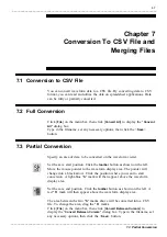
Страница 57: ...ny necessary options then click the Save button Specify an area of data to be converted on the waveform viewer Set the save start position Click the toolbar button as shown on the left Move the mouse pointer to the waveform display area The pointer will change into a black arrow Click the position where you want to start conversion A light blue S mark will then appear above the waveform display ar...

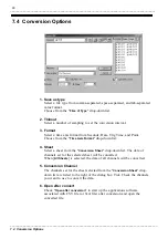
Страница 58: ...t a time axis format from Seconds Date Trig Time and Point Choose from the Time Axis Format drop down list 4 Sheet Select a sheet from the Conversion Sheet drop down list The data of channels set for the selected sheet will be converted When All Sheets is selected the data of all channels will be converted 5 Conversion Channel The channels set for the sheet selected from the Conversion Sheet drop ...

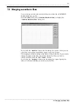
Страница 59: ...File menu select Combine Waveform Files to display the Combine Waveform Files dialog box If you click the Add File button the file dialog box opens so that you can select files for merging Added files appear in the list in order File merging is done according to the order of files in the list If you want to change the order of the files select from the list the files you want to change and then cl...

Страница 60: ...________________________________________________________________________________________ 7 5 Merging waveform files ______________________________________________________________________________________________ ...

Страница 61: ...t data saved on a PC card from the MEMORY HiLOGGER as MEM format binary file and measurement data acquired by Logger Communicator as HLW format binary file While the window of the waveform file you want to print is active click File on the menu bar choose Waveform Detail Print then Print to display the Print dialog box Complete the settings of the printer and printing area then click the OK button...

Страница 62: ...hart by selecting one from 1 Graph to 16 Graphs in the Format box for printing channels allocated to each chart The allocation of each channel is determined according to the split chart settings The selection of 2 Rows to 16 Rows determines the number of lines for printing the chart The print area on a page can be lengthened in the time axis direction Increasing the number of lines reduces the num...

Страница 63: ...hen printing on other size of paper choose Specify Margin 5 Margins Set the left right top and bottom margins in increments of 1 mm 6 Sheet Set the sheet to print Choose All or Only Displayed 7 Grid type Select a type of grid from OFF Standard Detail and Time axis 8 Gage Select a type of gage from Upper Lower and Detail Upper Lower prints the upper and lower limit values of each channel only Detai...

Страница 64: ...appear 14 Preview The print preview will be displayed according to the current detail print settings 15 Print The Print dialog box will appear to initiate printing 16 Advanced The Advanced Settings dialog box will appear This box allows you to select a line for the chart a character font or to edit various other settings 17 Default Initialize the detailed print setting 18 OK End the setting 19 Can...

Страница 65: ... Print Color Select from Color Gray scale or Black and white 2 Item Select a portion of the chart to which to apply the new settings The following settings are applied to the portion selected here 3 Line Width Select a width of the line used for the waveform and grid 4 Line Type Select the type of line used for printing the grid vertical line and horizontal line Solid line Dot line 5 Font Click th...

Страница 66: ...when this option is not selected 8 OK End the setting 9 Cancel Close the Advanced Settings dialog box without applying the changes While the window of the waveform file you want to print is active click File on the menu bar and choose Screen Print then Print The Print dialog box will then appear Complete the printer settings and click the OK button The printer will start printing using the current...

Страница 67: ...inting of all waveform files 1 Output Color Choose an output color option from Color Gray Scale and Black and White 2 Position When Print in the center of paper is checked the image is printed in the center of paper While the logging window of the waveform file you want to print is active click File on the menu bar and choose Logging Print The Print dialog box will then appear Complete the printer...

Страница 68: ...ng 1 Orientation Set the page orientation Choose Portrait or Landscape 2 Font Click the Font button to open the Font dialog box Select a printing font 3 Margins Set the left right top and bottom margins in units of 1 mm 4 Printer Display the Set Printer dialog box 5 Preview A print preview is displayed according to the current logging print settings 6 Print Displays the print dialog box to let you...

Страница 69: ...itoring 9 1 Startup You can monitor and control multiple MEMORY HiLOGGERs on a single PC via a LAN You can also send waveform data stored in logger memory to the PC Click the Start button on Windows Choose Programs HIOKI 9334 Logger Communicator Logger Monitoring to start up the logger monitoring program Logger Watcher To quit the program click the Exit button or click the close button in the top ...

Страница 70: ...on the logger leave the 8800 default setting For details see 2 4 LAN Settings Timeout Set the timeout limit to use during communications with the logger If the logger doesn t respond within the seconds set here the line will be disconnected Start watching at starting up Selecting this option will automatically begin monitoring when the logger monitoring program starts up Waveform receiving setting...

Страница 71: ...cancel the settings You can change the monitoring settings of loggers registered for the logger monitoring program Select a logger you want to change the monitoring settings from the list Click the Properties button to display the Properties dialog box The settings in this dialog box are the same as those in the Register dialog box Select a logger you want to delete from the list then press the De...

Страница 72: ...utton to close the dialog box without applying the settings When a logger is registered for monitoring the logger can be controlled on a PC For example you can start and end monitoring start and interrupt measurement and receive waveform data in logger storage memory Select a logger from the list and click Watch Monitoring of the logger will begin and current logger status will be displayed under ...

Страница 73: ...ing by the logger monitoring program is ended by operation on the logger Listener change Sent when another logger monitoring program starts monitoring When this event is received the 9334 stops monitoring the logger Selecting the monitored logger on the list and clicking End Monitor ends monitoring You can start or abort measurement of the logger being monitored Select the logger you want to contr...

Страница 74: ...ing program in IP Address of Monitor Server and enter the number set as the Listen Port No default 9000 of the monitoring program s general settings in Port Then turn ON Monitor Server to start monitoring by the logger monitoring program Any logger not registered for the logger monitoring program will be automatically registered Turn OFF Monitor Server to end monitoring When an event is received f...

Страница 75: ......

Страница 76: ......

Отзывы: