


Heinzinger electronic GmbH
Phone: +49 (0) 8031 2458 0
www.heinzinger.com
Anton-Jakob-Str. 4, 83026 Rosenheim
Fax: + 49 (0) 8031 2458 58
Germany
Page 32
ERS COMPACT
File name
Description
Section
iu<arbitrary_text>.csv
IU table for the XY function generator.
The name must begin with
iu
, the rest can be user defined.
3.11.12
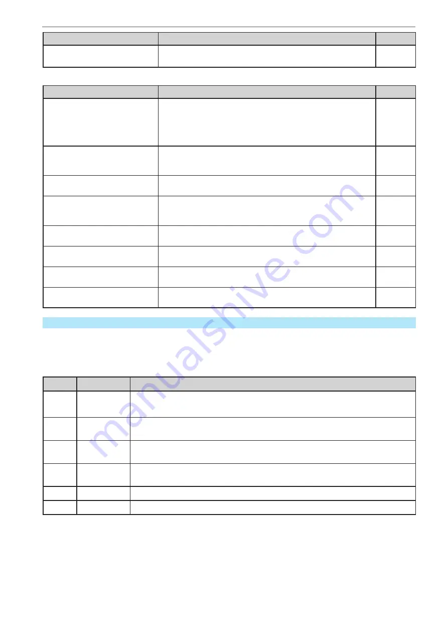
The control panel of the device can save the following file types and names to a USB stick:
File name
Description
Section
usb_log_<nr>.csv
File with log data recorded during normal operation in all modes.
The file layout is identical to the those generated from the Log
-
ging feature in EA
Power Control. The <nr> field in the file name
is automatically counted up if equally named files already exist
in the folder.
3.5.8
profile_<nr>.csv
Saved user profile. The number in the file name is a counter and
not related to the actual user profile number in the HMI. A max.
of 10 files to select from is shown when loading a user profile.
3.10
wave_u<nr>.csv
wave_i<nr>.csv
Sequence point data (here: sequences) of either voltage U or
current I from arbitrary function generator
3.11.10.1
battery_test_log_<nr>.csv
File with log data recorded from the battery test function. For
a battery test log, data different and/or additional to log data of
normal USB logging is recorded.
3.11.16.7
mpp_result_<nr>.csv
Result data from MPP tracking mode 4 in form of a table with 100
data groups (Umpp, Impp, Pmpp)
3.11.17.6
ERSC_pv<nr>.csv
PF function table data, as calculated by the device. Can be
loaded again.
3.11.13
ERSC_fc<nr>.csv
FC function table data, as calculated by the device. Can be
loaded again.
3.11.14
pv_record_<nr>.csv
Data from the data recording option in the extended PV function
according to EN 50530.
3.11.15.7
1.9.7
The control panel (Slave models)
The control panel of a Slave module is reduced to basic functions and consists of six colored LEDs, a pushbutton
and a USB port type B.
1.9.7.1
Status indicators (LED)
The six colored LEDs on the front indicate various statuses of the device:
LED
Colour
Indicates what when lit?
Power
orange / green
Orange = device is in boot phase or internal error occurred
Green = device is ready for operation
Remote
green
Remote control by master or any of the USB ports is active. In this situation, manual
control with button On/Off is locked.
Error
red
At least one unacknowledged device alarm is active. The LED can signalize all
alarms as listed in
“3.7. Alarms and monitoring”.
CC
yellow
Constant current regulation (CC) is active. It means, if the LED isn’t lit it indicates
either CV, CP or CR mode. Also see
“3.3. Operating modes”.
On
green
DC terminal is switched on
Off
red
DC terminal is switched off