


Heinzinger electronic GmbH
Phone: +49 (0) 8031 2458 0
www.heinzinger.com
Anton-Jakob-Str. 4, 83026 Rosenheim
Fax: + 49 (0) 8031 2458 58
Germany
Page 109
ERS COMPACT
• A max. of 64 units can be connected via Share bus.
•
When connecting the Share bus before a device had been configured as Master or Slave,
an SF alarm will occur
3.12.1.4
Wiring and set-up of the digital master-slave bus
The master-slave connectors are built-in and can be connected via network cables (≥CAT3, patch cable). After
this, MS can be configured manually or by remote control. The following applies:
•
A maximum of 64 units can be connected via the bus: 1 master and up to 63 slaves.
•
Only devices of same kind, i.e. power supply to power supply, and of the same model, such as ERSC 10080-
1000 4U to ERSC 10080-1000 4U.
•
Units at the end of the bus should be terminated, if necessary (see below for more information)
The master-slave bus must not be wired using crossover cables!
Later operation of the MS system implies:
•
The master unit displays, or makes available to be read by the remote controller, the sum of the actual values
of all the units
•
The ranges for setting the values, adjustment limits, protections (OVP etc.) and user events (UVD etc.) of the
master are adapted to the total number of units. Thus, if e.g. 5 units each with a power of 30 kW are connected
to a 150 kW system, then the master can be set in the range 0...150 kW.
•
Slaves are no operable as long as being controlled by the master
•
Slave units will show the alarm “MSP” in the display as long as they not have been initialized by the master. The
same alarm is signaled after a connection drop to the master unit occurred.
•
In case the function generator of the master unit is going to be used, the Share bus must be connected as well
►
How to connect the digital master-slave bus
1.
Switch off all units and connect the master-slave bus with network cables (CAT3 or better, cables not includ
-
ed). It doesn’t matter which of the two master-slave sockets (RJ45, backside) is connected to the next unit.
2.
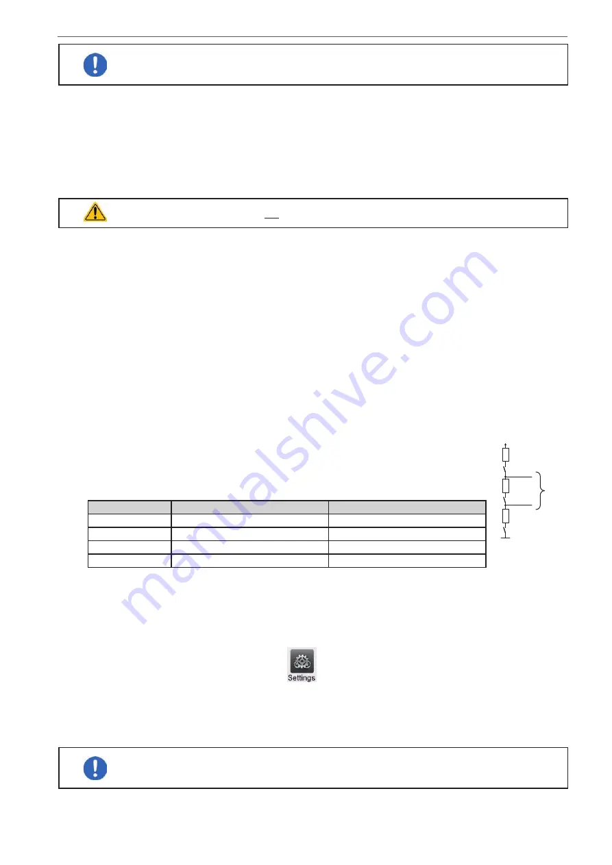
Depending on the desired configuration the units are then also connected at their DC
terminals. The two units at the beginning and end of the chain must be terminated, while
the master requires a separate setting. See table. Termination is done with internal elec-
tronic switches which are controlled from within the Settings menu of the device in group
“
Master-slave
”. Settings matrix for the units on the MS bus:
Position
Device with KE firmware < 2.08
Device with KE firmware ≥ 2.08
Master (at end) BIAS + TERM
BIAS + TERM
Master (central) TERM
BIAS
Slave (at end)
TERM
TERM
Slave (central)
-
-
R
R
+
B
A
BIAS
BIAS
MS
Bus
R
TERM
3.12.1.5
Configuring the master-slave operation
Now the master-slave system has to be configured on each unit. It’s recommended to configure all the slave units
first and then the master unit.
►
Step 1: Configuring all slave units
1.
While the DC terminal is switched off, tap on
in the main screen to access the
Settings
menu. Swipe
up to find group
Master-slave
and tap it.
2.
Tapping on the blue button text next to
Mode
will open a selector. By selecting
Slave
, if not already set, the
master-slave mode is activated and the device is defined as slave.
3.
Leave the Settings menu.
If function generator operation is setup for the master-slave system, the last step of the configu
-
ration requires to set global set values. These are important to be set to proper levels, because
they are transferred to the slave units, which else would remain being set to 0 V, 0 A and 0 W.
After this, the slave is fully configured for master-slave. Repeat the procedure for all other slave units.