background image

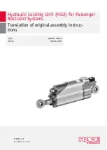
Hydraulic Locking Unit (HLU) for Passenger

Restraint Systems

Translation of original assembly instruc-

tions

B 6052-21

11

-2021  -1.7 en

Type:
ID no.:

System solution

HLU LE-X (M)

Содержание HLU LE-X

Страница 1: ...Hydraulic Locking Unit HLU for Passenger Restraint Systems Translation of original assembly instruc tions B 6052 21 11 2021 1 7 en Type ID no System solution HLU LE X M...

Страница 2: ...rand names product names and trademarks are not specifically indicated In particular with regard to registered and protected names and trademarks usage is subject to legal provisions HAWE Hydraulik re...

Страница 3: ...ion 14 3 2 3 Type DL EX Blocking against extension with comfort lock 14 3 2 4 Type DL RE Blocking against retraction with comfort lock 15 3 3 Instructions for the ride manufacturer 16 3 4 Markings 18...

Страница 4: ...pivot bearing clearance 40 8 3 5 Replace pivot mounts 40 8 3 5 1 Rod side rod end 40 8 3 5 2 Base side rod end 44 8 4 Electrics 47 8 4 1 Check and replace coil 47 8 5 Filling the hydraulic accumulato...

Страница 5: ...e the higher level system meets the requirements of DIN 13814 the Use of Work Equipment Directive 2009 104 EC the Directive 89 391 EEC and the national regulations of the country of use The informatio...

Страница 6: ...aterial damage Information to ensure the correct use of the product Safety symbols General safety symbol Draws your attention to additional safety information Slipping hazard Dragging hazard from movi...

Страница 7: ...Protective equipment Protective clothing Wear tted clothing without protruding parts Follow the safety data sheet of the hydraulic uid HAWE Hydraulik SE B 6052 21 11 2021 1 7 7 63...

Страница 8: ...xed Standard Name DIN EN 13814 Fairground and amusement park machinery and structure Safety of amusement rides and amusement devices ASTM F2291 Standard Practice for Design of Amusement Rides and Dev...

Страница 9: ...itory of the United States of America are excluded from said use Forces may only be transmitted to the locking unit by way of articulated lugs Use the product only after undergoing training by the sea...

Страница 10: ...between the hydraulic system and the machine frame Ensure that other people cannot enter the danger area Wear gloves and work shoes 2 4 Duties of the operator Observe and comply with regulations Do n...

Страница 11: ...ks and in how to use the product safely Specialist personnel Due to their technical training knowledge and experience specialists are able to assess and carry out the assigned work and can independent...

Страница 12: ...able in different sizes which vary in cylinder stroke direction of locking extension forces operating loads and maximum loads and supplies pressure according to the technical data specifications The o...

Страница 13: ...thread 5 V1 2 2 way directional seated valve with electromagnetically releasing check valve 12 Connection block 6 Piston type accumulator 13 Check valves with sealing caps 7 Double acting cylinder 3...

Страница 14: ...Opening the restraint system The hydraulic locking unit acts as a bar drive The piston rod 9 extends by extension force as soon as the 2 2 way valve 5 is energized and thereby opened The hydraulic pr...

Страница 15: ...hydraulic cylinder 7 from retracting under load Riders can use the restraint system as a handhold when entering and exiting the ride Further closing of the restraint system too tightly is prevented w...

Страница 16: ...d Get in touch with HAWE Micro Fluid GmbH Seat classes de ned in DIN EN 13814 Installation and control of the hydraulic locking unit is to be implemented by the ride manufacturer The following supplem...

Страница 17: ...ated simultane ously Operating modes The ride manufacturer must specify the modes for safe operation of the hydraulic locking unit within the ride Aids and tools Provide the following aids tools and m...

Страница 18: ...ion 0 0 Extend piston rod 1 0 Restraint system can be closed 1 0 Extend piston rod piston rod movable in both directions 1 1 Opening the restraint system 1 1 DL RE Restraint system locked for ride for...

Страница 19: ...trogen to escape at high pressure and penetrate deep into the body via the skin and eyes This can lead to severe and irreparable injury or even death Transport to be carried out only by instructed per...

Страница 20: ...2 Barbing Germany Tel 49 89 379100 6000 Claims for damage compensation can only be enforced during the applicable notification periods HAWE will not accept any liability for retrospective claims 4 3 S...

Страница 21: ...be crushed or shorn off if the system starts up unexpectedly Wear protective clothing Take precautions to prevent anyone from entering the danger zone throughout all commissioning or maintenance work...

Страница 22: ...nder head Protect the piston rod from damage to its surface Only trained specialist personnel is permitted to assemble the hydraulic locking unit DAMAGE Property damage from incorrectly installed hydr...

Страница 23: ...d only Do not pivot the rod end by more than 180 compared with the as delivered position The angle has not been changed to adjust the length because that is not permitted For speci ed torques and anti...

Страница 24: ...af x suitable warning signs to the barriers WARNING Danger due to signal interference at check valve The electromagnetically actuated check valve of the hydraulic locking unit can be subject to inter...

Страница 25: ...d to prevent overheating 1 Secure the ride against unintentional starting 2 Connect the solenoid valves to the control system The coil has a socket for 2 pin plugs Use cable with a matching plug accor...

Страница 26: ...Has the hydraulic locking unit been prevented from being used as a mechanical limiter for the bar structure Has the hydraulic locking unit been installed free of mechanical stress and is it protected...

Страница 27: ...em has cooled down before servicing or disassembling it 7 1 Switching on and off The hydraulic locking unit is supplied with power opened and locked via the ride s control system When opening the HLU...

Страница 28: ...th power supply connected Opening with power supply disconnected Opening under high static load WARNING Risk of injury in event of inadequate quali cation Improper operation of the emergency override...

Страница 29: ...unit as instructed under Opening under high static load 4 Make sure that all ride passengers can disembark safely 5 Check locking opening and holding functions in accordance with chapter Functional c...

Страница 30: ...ng unit and the restraint system can be opened This is an irreversible action The hydraulic locking unit must then be replaced Carry out the following actions only if unlocking the hydraulic locking u...

Страница 31: ...etely 2 Open the restraint system 3 Make sure that all ride passengers can disembark safely 4 Clean any areas contaminated by hydraulic uid immediately 5 Replace the hydraulic locking unit Get in touc...

Страница 32: ...cro Fluid GmbH immediately if you are in doubt as to whether or not the locking unit can be reused after the maintenance procedure The locking units should not be used again until clarification has be...

Страница 33: ...rd from hot surfaces and hydraulic uid A burn hazard results from directly or indirectly coming into contact with hot hydraulic uid and hot components of the hydraulic system Wear work gloves Arrange...

Страница 34: ...ator V Tapped plug on check valve droplets forming V Mechanism Check locking unit for external leakage Part of daily function testing page 38 Check emergency override button and clean if necessary V C...

Страница 35: ...cal damage and damp Greases oils lubricants Multi purpose grease Castrol Tribol GR 2 EP Oils lubricants WD 40 Cleaning products Universal thinner Staufen Remondis Medison GmbH Brake cleaner Keller Kal...

Страница 36: ...ironmental effects when tted with a rubber cap and cleaning it is then also much easier Aids tools materials Type speci c design of the tool to operate the emergency override page 17 Listed cleaning a...

Страница 37: ...locking unit 6 Start up the hydraulic locking unit in the ride chapter Starting up the hydraulic locking unit page 26 7 The locking unit must be replaced if damaged Get in touch with HAWE Micro Fluid...

Страница 38: ...mergency override can result in severe injury and damage to property The emergency override may only be operated by trained personnel or instructed persons After the emergency override has been operat...

Страница 39: ...mmission the hydraulic locking unit if the paint markings are damaged between the rod end and piston rod or rod end and connection block Aids tools materials See instructions for replacing rod ends in...

Страница 40: ...E approved pivot mount used Rod end replaced in accordance with chapter Replace pivot mounts page 40 8 3 5 Replace pivot mounts Pivot mounts are wearing parts which are subject to load dependent wear...

Страница 41: ...inst inadvertent restarting 2 Remove the hydraulic locking unit from the ride 3 Clamp the hydraulic locking unit in a vise so that the rod end is easily accessible Use jaw caps Be careful not to damag...

Страница 42: ...the nut and degrease it a When using the brass brush make sure that no particles fall into the gap between the piston rod and seal b Cover the area c Clean the piston rod 10 Apply threadlocking adhes...

Страница 43: ...torque according to the technical drawing Wrench size 22 2 wrench size 24 1 13 After tightening to torque mark the nut and rod eye with threadlocker paint 14 After 24 hours setting time the hydraulic...

Страница 44: ...l data DAMAGE Damage due to heat up of the foot side pivot mounts Heating up of the foot side pivot mounts will damage seals and cause leaks in the hydraulic system Never heat the base side rod ends U...

Страница 45: ...e internal thread of the cylinder base with the tap M 16 Do not damage the thread 7 Blow off the cylinder base s thread with compressed air 8 The gradation in the nut thread faces toward the piston ro...

Страница 46: ...l thread with adhesive 10 Screw the rod end with nut into the thread of the cylinder base Comply with the minimum screw travel L 1 in the customer drawing 11 Apply threadlocking adhesive to the rod en...

Страница 47: ...trics 8 4 1 Check and replace coil Maintenance intervals Only if there are malfunctions Aids tools materials New coil as per technical data sheet Multimeter 2 small size 4 screwdrivers to remove housi...

Страница 48: ...ure tube 1 is exposed Take the coils 2 out of the solenoid housing 3 7 Center and slide the new coil onto the pressure tube 8 Push the solenoid housing over the coil and pressure tube so that the slot...

Страница 49: ...laced DANGER Hydraulic accumulator will explode if used incorrectly or lled incorrectly Serious injury or death The hydraulic accumulator s maximum operating pressure lling pressure and temperature ra...

Страница 50: ...ogen supply 1 Connect nitrogen controller to your nitrogen bottle 2 Make sure that the discharge throttles 2 on the controller are shut 3 Open the nitrogen bottle s valve 1 4 Set the nitrogen controll...

Страница 51: ...nto accumulator 4 3 Open the ller screw 2 with a size 6 hex key 1 2 turn 4 Screw HAWE lling unit DFM 400 onto adapter Make sure that the lling unit has an O ring Lay the O ring into the guide slot 1 S...

Страница 52: ...from hydraulic accumulator 7 Screw on the accumulator s tapped plug with a size 8 hex key see technical drawing for torque 8 6 Functional check It must be ensured that valves switch reliably and are...

Страница 53: ...the restraint system mechanism If during the check the lock position on the cylinder changes by more than 1 mm in the locking direction or if oil leaks out the locking unit is faulty Replace the lock...

Страница 54: ...t Type RE DL RE Check the accumulator pressure by a slack test Extend the restraint system at the maximum permissible piston rod extension speed speci ed in the data sheet There must be no slack 4 Not...

Страница 55: ...traint system as per the switching logic page18 2 Adjust the restraint system using the adjuster tool Make sure that at the start of the load test the permissible play of the restraint system and any...

Страница 56: ...ry or death Depressurize the hydraulic system including the pressure tank Secure the hydraulic system against unintentional restart Check components for correct assembly before pressure is applied Obs...

Страница 57: ...the instructions on page 30 3 Drain the hydraulic uid 4 The hydraulic locking unit has been depressurized and can be disassembled 5 Dispose of all hydraulic locking unit components in accordance with...

Страница 58: ...trained personnel or instructed persons After the emergency override has been operated the locking opening and holding function as well as the drift must be checked as per the functional check proced...

Страница 59: ...laced Contact HAWE Piston rod does not extend fully restraint system does not open enough Nitrogen pressure loss in piston type accumulator Top up according to the data sheet specifications using the...

Страница 60: ...GmbH Seat classes de ned in DIN EN 13814 You will be provided with the hydraulic and electrical data of the individual product variants as accompa nying external documentation with the product speci c...

Страница 61: ...d international road and rail transport and transport by inland waterway UN 3164 Nicht beschr nkt auf Grund der Bestimmung des Europ ischen bereinkommen ber die internationale Bef rderung gef hrlicher...

Страница 62: ...ical data sheet Contact details Headquarters HAWE Hydraulik SE Einsteinring 17 85605 Aschheim Germany e mail info hawe de www hawe com Phone 49 0 89 37 91 00 1000 Barbing HAWE Micro Fluid GmbH Borsigs...

Страница 63: ...electronic components are perfectly coordinated with the hydraulic components and simplify ing control signal evaluation and fault detection The intelligent system solutions reduce energy consumption...

Отзывы: