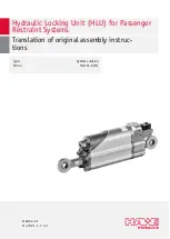
check valve, and two pressure ports. The piston type accumulator preloads the unit to a dened pressure,
and captures the oil volume displaced by the piston rod when retracting. The piston type accumulator
allows the locking unit’s piston rod to extend at different speeds and forces depending on the pressure
ratios.
The seated valve allows oil ow in one direction only, blocking the other direction. Oil ow in both
directions is possible in normal operation by way of the electromechanical actuator (3) and/or (4). In
an emergency, the valve (4) must be actuated manually for the purpose. The pressure ports are used for
lling the unit with oil and configuring its pressure at the factory (
WARNING
Danger to life if valves V1 and V2 are energized while running
If valves V1 and V2 are energized while the ride is running, the restraint system might release and riders
might suffer fatal injury.
■
Keep valves V1 and V2 de-energized during operation.
■
Observe the switching logic on page (
3.2.1 Type EX: Blocking against extension
Primary function:
Locking the restraint
system
The hydraulic locking unit is connected via the rod ends (1) and (11) to the ride’s restraint system (such
as the shoulder bar mechanism), and can be unlocked manually/electrically. When the restraint system is
closed, the piston rod (9) of the hydraulic cylinder (7) retracts, lling the hydraulic accumulator (6). This
builds up and maintains a hydraulic pressure. The restraint system is closed.
The piston rod (9) is prevented from extending by the check valve (5). The restraint system is thus
locked.
Secondary function:
Opening the restraint
system
The hydraulic locking unit acts as a bar drive. The piston rod (9) extends by extension force as soon
as the 2/2-way valve (5) is energized and thereby opened. The hydraulic pressure is relieved, and the
hydraulic locking unit’s restraint system (such as the bar) is actively opened.
3.2.2 Type RE: Blocking against retraction
Primary function:
Close and lock restraint
system
The hydraulic locking unit is connected via the rod ends (1) and (11) to the ride’s restraint system
(such as the shoulder bar mechanism), and can be unlocked manually/electrically. When the restraint
system is closed, the piston rod (9) of the hydraulic cylinder (7) is extended. The hydraulic pressure in
the accumulator (6) is relieved, ensuring correct internal ow of hydraulic uid. The restraint system is
closed.
The piston rod (9) is prevented from retracting by the check valve (5). The restraint system is thus
locked.
Secondary function:
None
The hydraulic locking unit type RE generates only low piston extension forces by design. When the 2/2-
way valve (5) is energized, and thereby opened, the piston rod (9) of the hydraulic cylinder (7) remains
extended. The piston rod can be moved in the retraction and extension directions.
It is not possible to drive the restraint system's opening motion by way of the hydraulic locking unit. The
low extension forces produce a force that closes the restraint system. An additional system (such as a
gas spring or leg spring) is therefore required to drive the opening motion and keep the restraint system
(such as the bar) open.
3.2.3 Type DL (EX): Blocking against extension with comfort lock
The hydraulic locking unit is connected via the rod ends (1) and (11) to the ride’s restraint system (such
as the shoulder bar mechanism).
14/63
B 6052-21 -
11
-2021 - 1.7
HAWE Hydraulik SE


