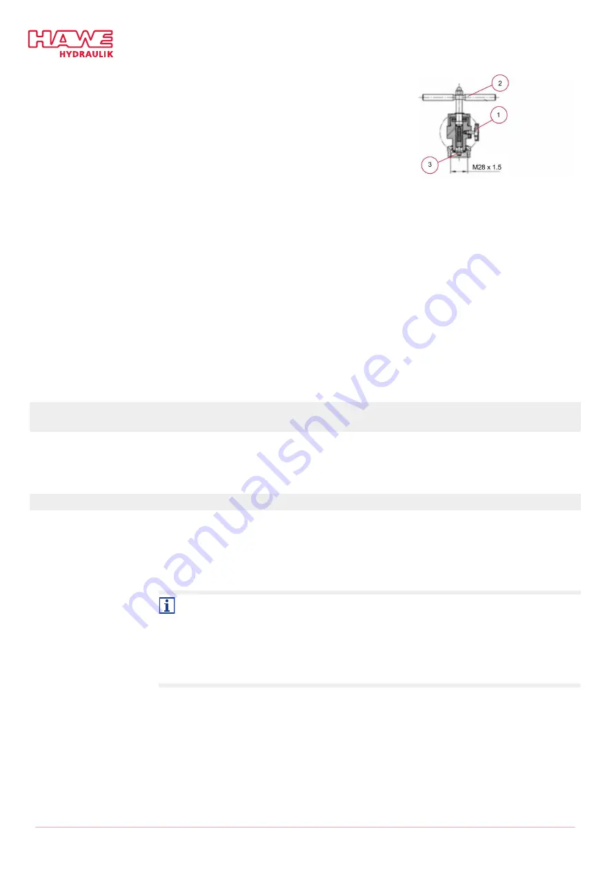
Fill:
1. Connect the nitrogen controller to the lling unit with a
hose.
2. Close drain valve (1).
3. Turn the lling unit’s handle (2) back and forth until the
lling unit’s hex key (3) engages in the ller screw.
✓
Piston rod fully extended
4. Slowly unscrew the ller screw by turning the handle
counter-clockwise slowly, so that gas can ow over.
5. Slowly open the nitrogen controller’s discharge throttles.
6. Check and adjust pressure P1 in the hydraulic accumula-
tor's pressure gage (20).
- Observe one minute of settling time.
7. Stop lling when P1 has been reached in the hydraulic
accumulator.
After lling:
1. Close ller screw by handle.
2. Shut discharge throttle on nitrogen controller.
3. Slowly open drain valve.
4. Disconnect lling unit from adapter.
5. Close the ller screw with a size 6 hex key.
(see technical drawing for torque)
6. Disconnect adapter from hydraulic accumulator.
7. Screw on the accumulator’s tapped plug with a size 8 hex key. (see technical drawing for torque)
8.6 Functional check
It must be ensured that valves switch reliably and are tight over the valve seat when closed, and that
leaks are reliably detected. The ll pressure and accumulator preload pressure must also be monitored
regularly.
8.6.1 Locking function
Interval
Daily
Aids, tools, materials
■
Distance measuring systems (e.g. caliper gage, etc.)
■
Tool to remove any component covering
To check the locking function, the locking unit is loaded with 10 to 20% of the permissible
dynamic locking force in the opening direction for 3 to 5 seconds.
Friction losses and lever forces of the seat kinematics (transmission ratios) must be taken into
account when converting the force to be applied to the restraint system.
If during the check the ‘locked’ position on the cylinder changes by more than 1 mm, or if oil leaks
out, the locking unit is faulty, and must be replaced.
52/63
B 6052-21 -
11
-2021 - 1.7
HAWE Hydraulik SE


