57
2420344510 E
11.11
AUS
Telescopic handlers
C
- Pre-operation and controls
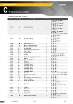
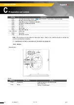
(*) : Identification of the components on the electrical diagrams
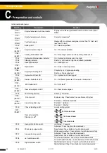
1
: Do not exceed 3000 tr/min (3000 rpm). Do not run the engine speed into the red zone.
2
: Service the machine as set out in this manual (
Section H - Lubrication and
maintenance).
3
: The ECU (P191) indicator flashes to indicate an internal malfunction.
When the machine switches downgraded mode, certain movements can be limited or
prohibited to safeguard the operator's well being (
Section H 23 - Operating incidents).
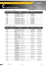
P213
Beacon switch
On : Press top of switch downwards
Off : Press bottom of switch downwards
P214
Parking brake switch
Activated : Press top of switch downwards
Deactivated : Press bottom of switch downwards
P215
Road mode selection switch
On : Press top of switch downwards
Off : Press bottom of switch downwards
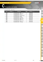
P220
(HL163)*
Water in GO indicator
On : Presence of water in diesel fuel
P221
(SA187)*
Fork/Winch Selector (Option)
Fork position : Center
Winch position : Rotate to left
P222
Emergency pump / Radio-control
Selector (Option)
Back-up pump power supply : Rotate to right and hold
Drive in neutral position : Center
Radio-control position : Rotate to left
P224
Drive speed 1 indicator
On : Speed 1 engaged
P225
Drive speed 2 indicator
5
On : Speed 2 engaged
Flashing : Do not shift gear
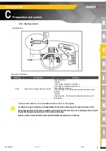
The stabilisers only increase stability and load capabilities if they are used correctly. Using stabilisers on
soft surfaces can cause the machine to tip over which can result in serious injury. Always make sure that
the surface on which the machine operates, is capable of supporting the combined weight of the machine
and the load.
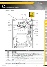
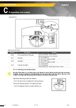
For high-speed driving and any driving on public roads :
• Only use the "Front steer wheels" mode.
• Check the alignment of the rear wheels : The "Rear wheels aligned" indicator (P192) must be switched
on.
Driving mode must be realigned :
• At the start of each day.
• At least once a day.
• If a misalignment problem is observed between the front and rear axles.
Follow the instructions below to realign the driving system :
1.
Select the "Front steer wheels" mode. Rotate steering wheel slowly to
bring the rear wheels to the right position. The "Rear wheels aligned"
indicator (P192) must be switched on. Continue to rotate steering wheel
slowly until you see the front wheels aligned.
2.
Select the "Synchronised axle" mode again. Check the realignment by
carefully driving the machine a short distance.
Marking
Description
Function
Содержание HTL 3210
Страница 2: ...2 2420344510 E 11 11 AUS Telescopic handlers...
Страница 12: ...12 2420344510 E 11 11 AUS Telescopic handlers...
Страница 39: ...39 2420344510 E 11 11 AUS Telescopic handlers C Pre operation and controls Localization right view HTL3510...
Страница 40: ...40 2420344510 E 11 11 AUS Telescopic handlers C Pre operation and controls Localization cab view...
Страница 42: ...42 2420344510 E 11 11 AUS Telescopic handlers C Pre operation and controls Localization view from above HTL3510...
Страница 43: ...43 2420344510 E 11 11 AUS Telescopic handlers C Pre operation and controls Localization rear view...
Страница 74: ...74 2420344510 E 11 11 AUS Telescopic handlers D Operation...
Страница 80: ...80 2420344510 E 11 11 AUS Telescopic handlers E Attachments HTL4010 load capacity chart...
Страница 146: ...146 2420344510 E 11 11 AUS Telescopic handlers F Emergency procedure...
Страница 158: ...158 2420344510 E 11 11 AUS Telescopic handlers H Lubrication and maintenance 4 Lubrication and maintenance schedule...
Страница 159: ...159 2420344510 E 11 11 AUS Telescopic handlers H Lubrication and maintenance...


