APEX
™
Exciter Incorporating FLO
™
Technology
Navigating the LCD Display Screens
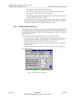
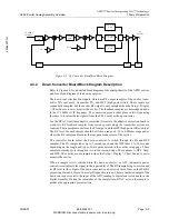
RTAC Operating Procedures, Main Screen.
Page: 3-56
888-2604-001
03/08/07
WARNING: Disconnect primary power prior to servicing.
3.7.2
From Adaptive Precorrection Board Status Screen
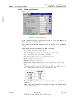
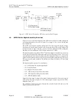
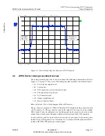
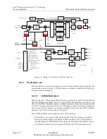
Each of the three RF sample feedbacks below has a bar graph on the adaptive precorrection
board status screen. The yellow (upper) bar indicates average power level and the blue
(lower) bar indicates peak level. The RF input sample is within the correct power range
(-30 to 0 dBm) when both bars are within the center range of the window. The bar graphs
show the signal level at the output of the sample AGC circuit. If any input sample is outside
the allowable power range, the bars for that input will be at an extreme end of the widow
and that input will be faulted.
If one or more RF samples to the ADC exceeds maximum allowable level the ADC Over
Range indication on the adaptive precorrection board status screen will be faulted.
Note
Maximum input level for the three feedbacks mentioned above
should not exceed 0 dBm. Excessive input levels (+20 dBm or
greater) will cause faults for the ADC and feedback inputs and can
also cause crosstalk between inputs and/or damage to the exciter.
3.7.3
From Down Converter Board Status Screen
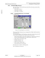
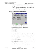
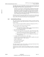
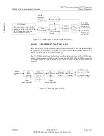
Two entries on the IF &RF Processing Status > Down Converter Status screen are of
interest to RTAC operation, They are:
• RF Sample: This indicates which down converter sample is currently active.
• RF Level: RF level (taken after the AGC circuit) for the current sample. It typically
ranges between 0.5 to 1.0 Vdc for samples of proper input power range.
If known good samples are present at the exciter inputs, and they are not all being sampled,
or their level is wrong, the down converter diagnostics screen should be checked.
3.7.4
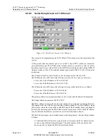
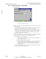
From Down Converter Diagnostics Screen
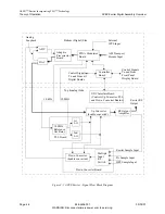
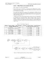
• RF Sample Select: (Automatic, Exciter, Amplifier, or HPF).
When Automatic (normal mode) is selected, the controller board causes the down
converter to switch between the Amplifier, and HPF inputs. The exciter is only sam-
pled when the Setup > Display > Chart Source is set to monitor the exciter.
When not in automatic mode, the down converter is locked to the Exciter, Amplifier,
or HPF sample input.
• RF Sample AGC: (Enabled or Disabled), enabled mode is normal.
When enabled is selected, the level of each RF sample (at the output of the down con-
verter) is adjusted to the correct level for the ADC (analog to digital converter).
When disabled, for test purposes, the level of each RF sample must be manually set
by the blue up and down gain arrows at the bottom of the screen. The possible range
is 0 to 4096.
• RF Sample tells which sample input to the down converter is currently active.
• RF Level: This is the current RF sample level (taken after the AGC circuit). It typical-
ly ranges between 0.5 to 1.0 Vdc when the input sample is within proper power range.
• Gain: This control is only active when RF Sample AGC (on this screen) is defeated. It
is used to set the down converter gain so that the sample level falls between 0.6 and
1.0 Vdc.

