APEX
™
Exciter Incorporating FLO
™
Technologyr
APEX Exciter Analog Assembly Overview
Theory of Operation
26
04s40
0.fm
03/08/07
888-2604-001
Page: 4-9
WARNING: Disconnect primary power prior to servicing.
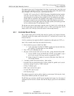
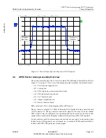
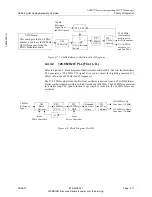
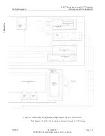
Figure 4-5 Up Converter Simplified Block Diagram.
4.4.2
Down Converter Board Block Diagram Description
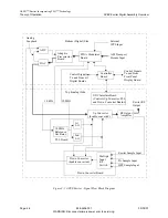
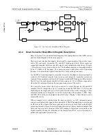
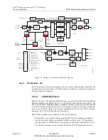
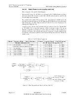
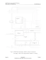
Refer to Figure 4-6 for a detailed block diagram of the analog chassis of the APEX exciter,
and for a block diagram of the down converter.
The down converter has four inputs, which are RF output samples of the exciter, trans-
mitter IPA (not used), transmitter PA, and HPF (high power filter). These inputs are
sequentially sampled, but the exciter RF output is only sampled when the Setup > Display
> Chart Source is set to monitor the exciter. The feedback samples are heterodyned down
to the 11.1 MHz 1st IF frequency. The conversion process takes place in two steps using
the same to local oscillator signals (from the PLL board) as the up converter.
For the RTAC (real time adaptive correction) circuits in the adaptive correction board to
work, two RF feedback samples from various points along the transmitter system are
required. These samples come from the PA output, and the HPF (high power filter) output.
The RF level for each sample should be within a range of -30 to 0 dBm average power
where the RF sample cables enter the rear panel connectors of the exciter.
The controller board causes the down converter to switch through the PA and HPF
samples. The PA sample takes up to 5 seconds each and the HPF takes 5 to 90 seconds
depending on the length and type of waveguide entered in the exciter setup page. These
samples normally cycle through in two to four second steps. The sequence is HPF, Amp,
and HPF. The exciter is only sampled when the Setup > Display > Chart Source is set to
monitor the exciter.
When a sample is first switched into the down converter, an APC (automatic power
control) circuit adjusts the signal to the required level. The RF sample being converted and
its RF level (at the output of the down converter) can be viewed in real time on the IF &RF
processing Status 4/4 Down Converter Diagnostics screen. The level adjusted output of the
down converter is sent to the input of the ADC (analog to digital converter) board in the
digital assembly. During the remainder of the sample time, RTAC acts on the sample to
produce the appropriate precorrection.
10.76 MHz
Input
2
nd
LO
30 MHz
LPF
140 MHz
SAW
1
st
LO
Switch
174-213 MHz
Filter
470-806 MHz
Filter
54-85 MHz
Filter
Switch
On
Channel
Detector
Detector
Gain
Control
11.1 MHz
IF Input

