APEX
™
Exciter Incorporating FLO
™
Technology
Basic Operating Procedure
Navigating the LCD Display Screens
26
04s30
0.fm
03/08/07
888-2604-001
Page: 3-1
WARNING: Disconnect primary power prior to servicing.
3
Navigating the LCD Display Screens
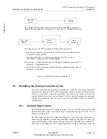
Operating the APEX exciter requires knowledge of two sets of controls.
First is the power off/on switch, which is not normally used if the exciter is mounted in a
transmitter, but could be used if the exciter is used as a signal source apart from a trans-
mitter. The power off/on switch is located on the right side of the exciter rear panel when
facing the rear of the exciter.
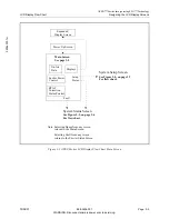
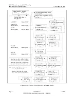
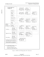
The second and most important part of exciter operation is knowledge of the LCD display
touch screens, which is covered in the remainder of this chapter.
3.1
Basic Operating Procedure
After the exciter has been installed and set up, the two most often used operating functions
are raising or lowering the exciter RF output power and locating exciter faults if a malfunc-
tion should occur. These two topics will be addressed before the subject of the LCD screen
navigation is covered.
3.1.1
Raising or Lowering Output Power
The average output power of the exciter in mW is displayed on the main screen. Exciter
output power adjustment soft keys are also included on the main screen, and appear as
arrows to the left and right of the output power display.
On the main screen, output power can also be set by touching the numbers in the power
display. This brings up a number pad where a new value for output power (between 0 and
250 mW average power) can be entered. When new value is entered, it is accepted by
touching Done or the old power retained by pressing Cancel.
Exciter power raise and lower can also be controlled remotely. In most transmitters, exciter
power is controlled from the transmitter, with transmitter output power controlled locally
and remotely by a separate circuit. In some transmitters the exciter output power control is
the transmitter output power control, and is available by remote control.
3.1.2
Exciter Fault Display - Red
The exciter includes several LCD status screens which display normal or fault operating
conditions. If a fault occurs within the exciter, a red FAULT button appears at the bottom
of each screen. Touching the fault button switches to the System Status screen, which will
display a FAULT status beside the offending section of the exciter. Touching the faulted
box causes the status display for that box to appear. This display gives additional informa-
tion concerning the problem within that section and will point to a circuit board and/or a
signal condition.
3.1.2.1
Fault Warning - Yellow
When status screen parameters approach their limit, a yellow warning will replace the
green OK indication at the bottom of the screens.
When VSWR foldback is active the system control light on the front panel will be lighted
yellow.

