APEX
™
Exciter Incorporating FLO
™
Technology
Maintenance and Troubleshooting
Exciter Troubleshooting Flow Charts
Page: 5-12
888-2604-001
03/08/07
WARNING: Disconnect primary power prior to servicing.
5.5
Exciter Troubleshooting Flow Charts
The four charts in this section offer some initial troubleshooting guides for the more
common setup related problems encountered with the APEX exciter. More detailed trou-
bleshooting information is available in the succeeding sections of this chapter.
All of the exciter setup functions and normal operation instructions as well as many of the
diagnostic functions are controlled by the front panel LCD touch screen display. As a
result, many of the troubles experienced with the Apex exciter and transmitter RF system
will be due to improper exciter touch screen settings.
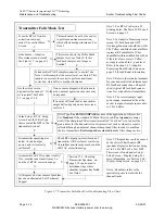
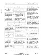
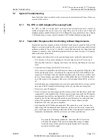
The following four flow charts are an attempt to guide the user through some of the more
typical touch screen involved problems. An attempt was made to structure the charts in a
top to bottom and left to right simple to complex format. The four charts include:
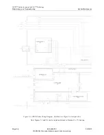
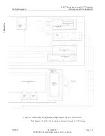
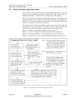
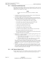
Figure 5-5, Frequency Error Troubleshooting Flow Chart, on page 5-12.
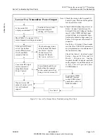
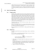
Figure 5-6, Low or No Output Power Troubleshooting Flow Chart, on page 5-13.
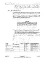
Figure 5-7, Transmitter Fails Mask Test Troubleshooting Flow Chart, on page 5-14.
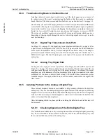
Figure 5-8, Transmitter Has Excessive MER Troubleshooting Flow Chart, on page 5-15.
Figure 5-5 Frequency Error Troubleshooting Flow Chart
Is Exciter set to
correct frequency,
Exciter Setup Screen?
N
Y
Set to correct frequency
Frequency Error, See Notes 1 and 2
using Setup Screen.
Is Exciter frequency
offset setting correct,
Exciter Setup Screen?
N
Y
Is the 1PPS GPS reference
Y
N
signal present at J18 at
N
Y
Enter 0 (no offset) or
correct value (in Hz) using
Exciter Setup Screen.
Offset limit is +/- 50000
Hz.
See Section 5.1.2.1, Measuring Center
Channel Frequency, on page 5-6
Note 2:
the exciter rear panel
If the 1PPS reference is not
present, the exciter will
flywheel until its time out is
met, then the exciter will mute.
If these procedures do
not correct the problem,
contact technical support.
Caution, unless the frequency counter
is locked to an accurate external refer-
ence, such as the 10 MHz output of a
GPS receiver, it may have an error of
20 Hz or more. Counters will exhibit
greater error at UHF then at VHF.
Note 1:
Check the FPGA modulator board
termination jumper (JP1) for the
correct termination, choices are Pins
1 - 2 for 50 ohms or 2-3 for high
impedance. See Section 2.4, Installa-
tion of the GPS 1PPS Signal, on
page 2-2.
Check the Status > Digital Processing > Flo FPGA
Registers > Flo FPGA Status 2/5 screen. The
average frequency error must be less than +/- 1 Hz.
If outside this range, the exciter will be muted. The
error should gradually reduce with time.
See Note 2.
Frequency must be set to
a whole MHz.
Is the signal level within
the 0 to 5 V TTL limits

