APEX
™
Exciter Incorporating FLO
™
Technology
Installation
Retrofitting Into Existing Transmitter System
Page: 2-4
888-2604-001
03/08/07
WARNING: Disconnect primary power prior to servicing.
filter has been characterized the Apex exciter applies pre-correction such that the response
and delay have been optimized at the filter output. In addition to characterizing the mask
filter, any transmission line or antenna VSWR present at the monitoring point will also be
compensated.
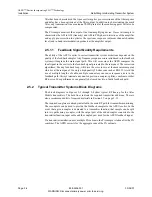
The PA sample monitors the output of the final amplifying device. It uses this sample to
characterize the AM to AM (linearity) and AM to PM (phase) distortions of the amplifier
and apply pre-correction to optimize the spectrum response (adjacent channel shoulder
level) and in band intermodulation products at the amplifier output.
2.5.1.1
Feedback Signal Quality Requirements
The ability of the APEX exciter to correct transmitter system distortions depends on the
quality of the feedback samples. Any frequency response errors introduced in the feedback
system will degrade the main signal path. This will occur since the APEX compares the
ideal signal in the exciter to the feedback signal presented to the rear panel. The correction
algorithms, like any feedback loop, will drive the error to zero at the measurement point,
which is at the rear panel. Use only a high quality 50-ohm coax such as RG223. Avoid the
use of multiple lengths of cable; multiple connectors can cause response errors in the
feedback path
.
Always terminate any unused ports on a coupler, splitter, combiner or other
RF device. Poor performance can generally be traced back to a faulty feedback path.
2.5.2
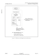
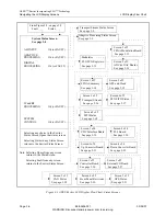
Typical Transmitter Systems Block Diagrams
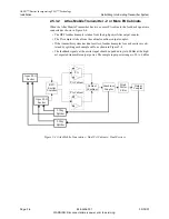
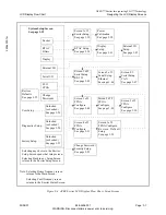
The block diagrams in Figures 2-3 through 2-4 show typical RF line-up for the Atlas
Mobile transmitters. The bold lines indicate the required transmitter additions. There is
also a recommended list of required materials in Section 2.7 on page 2-11.
The required couplers are already installed in the main RF path for transmitter monitoring.
These couplers can be used to provide the feedback samples to the APEX exciter. In the
event that a given coupler is dedicated to a transmitter function, that sample can be split
into two paths using a coupler, with the output port of the added coupler connected to the
transmitter function input cable and the coupled port used for the APEX feedback signal.
If a transmitter installation uses multiple PA cabinets, the PA sample is taken after the PA
combiner. The APEX corrects for the aggregate sum of the PA cabinets.

