


Chapter 8 Safety Settings
98
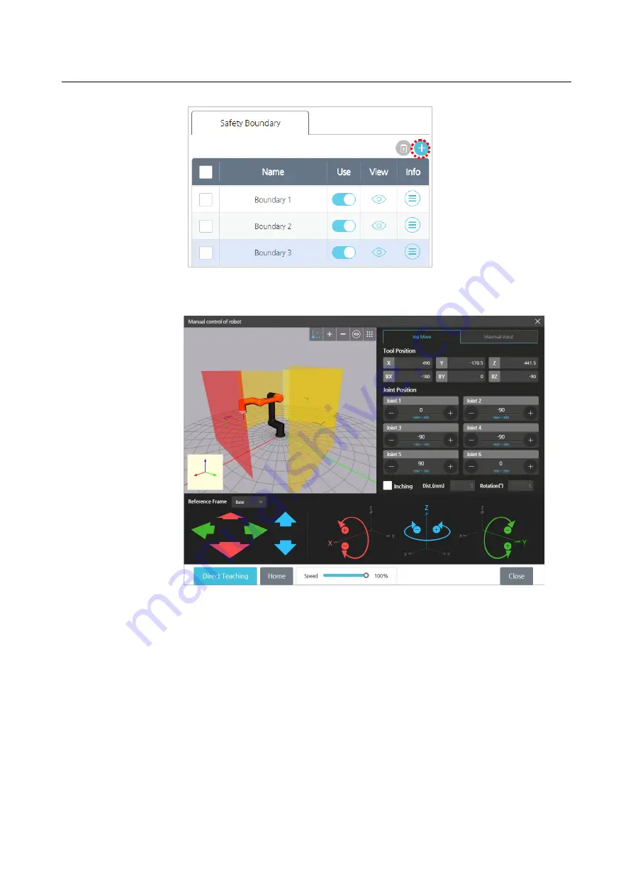
2.
In the
Manual Move
screen, use jog control and
Direct Teaching
button to set
the boundary position.
For more details on the
Manual Move
screen, refer to 5.3 Manual Move
Screen.
Your safety boundary will be created in a location that is separated from the
center axis of the flange as much as the TCP length set in the TCP.
3.
To save the settings, press the
OK
button.
Viewing safety boundary planes
Press the icon in the
View
column to hide or unhide the safety boundary plane in the
preview screen.
Содержание HCR-5
Страница 1: ...HCR 5 Collaborative Robot User Manual Aug 2019 V 2 001 ...
Страница 2: ......
Страница 14: ......
Страница 96: ...Chapter 8 Safety Settings 96 ...
Страница 101: ...Chapter 8 Safety Settings 101 3 Press the OK button ...
Страница 177: ...Chapter 12 Device Settings 177 B When the scanning location and the robot s location are shifted by X ...
Страница 188: ...Chapter 15 Maintenance 188 4 When the confirmation window appears press YES ...
Страница 192: ...192 Appendix B Certification Safety ...
Страница 193: ...193 ...
Страница 194: ...194 MD Machinery Directive ...
Страница 195: ...195 LVD Low Voltage Directive ...
Страница 196: ...196 EMC Electro Magnetic Compatibility ...
Страница 197: ...197 Cleanroom Body ...
Страница 198: ...198 Cleanroom Controller ...
Страница 199: ...199 Appendix C Dimensions for Installation ...
Страница 200: ...200 Appendix D Tool Flange Cross Section The tool flange is designed suitable for ISO9409 1 50 4 M6 ...
Страница 205: ......