background image

Chapter 8   Safety Settings 

104 

For 

reference 

Pressing the 

Apply/Cancel

 buttons simultaneously applies 

the safety 

boundary of the working area

 to 

the safety boundary of the 

tool

.


8.4 

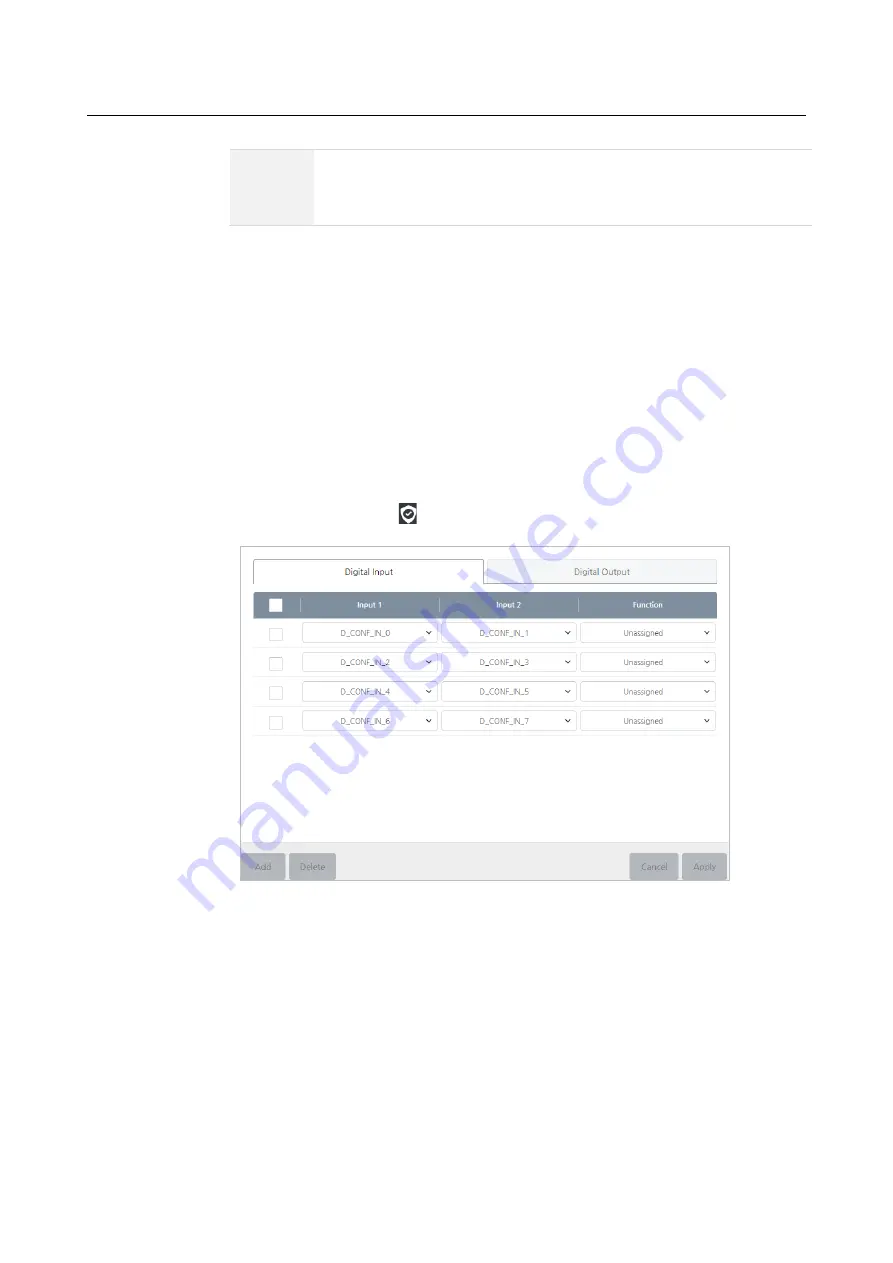
Setting Redundant I/O 

To guarantee the safety of the I/O terminal or input/output the important data, you can 
opt for using a redundant I/O, not a single I/O.  If you set the redundant I/O, you are 
no longer checking a single I/O value. Instead, the two designated inputs or outputs 
check the High or Low signals to determine validity of values. 

In the main menu, press 


Safety Setting

 > 

Redundant I/O


There are two tabs - digital input and digital output. Select the tab to set and proceed as 
follows. 


In case of digital inputs, the function will operate if the input is high or low. 


In case of digital outputs, the high or low signal is sent for the assigned function. 

1.


Press the


Add

 button. 

2.


Select an I/O terminal to be used as redundant I/O.  

3.


Set the function to be assigned. 

Содержание HCR-5

Страница 1: ...HCR 5 Collaborative Robot User Manual Aug 2019 V 2 001 ...

Страница 2: ......

Страница 3: ... system concepts and installation issues The actual product may differ from the manual Please keep this manual in a safe place for future reference Voltage 100 240VAC 50 60Hz 1kW It should be connected to the neutral cable which is connected with grounding line with one phase of the 3 phase cables Status of load installation Load is not exceeding the payload of Robot Please check the grounding lin...

Страница 4: ...rs are responsible for any damages caused by their misuse or modification of the patent rights for the equipment The information provided by the manual is deemed trustworthy by Hanwha Precision Machinery Co Hanwha Precision Machinery Co is not responsible for any situations arising due to inaccuracy or typo in the content of the manual The information provided in the manual is subject to change wi...

Страница 5: ...ACHING PENDANT 23 Front 23 Rear 24 1 7 AXIAL COORDINATES AND OPERATIONAL RANGE 25 1 8 ROBOT S WORKING RANGE 27 1 9 MAXIMUM LOAD CAPACITY FOR THE TOOL 28 CHAPTER 2 SAFETY 29 2 1 SAFETY MARKS IN THE USER MANUAL 29 2 2 GENERAL SAFETY CAUTIONS 30 2 3 INTENDED USE 31 2 4 POTENTIAL DANGERS 32 2 5 LIMITATION OF LIABILITY 32 2 6 TRANSPORTATION 33 2 7 EMERGENCY STOP 34 Using emergency stop 34 Canceling eme...

Страница 6: ... O 45 3 9 CONFIGURING THE SAFETY INPUT 48 Initial safety configuration 49 Connecting the emergency stop button 50 Safety protection stop and restart 50 3 10 CONFIGURING THE GENERAL DIGITAL I O 51 Load control with digital outputs 51 Digital input control using buttons 52 Communicating with other equipment or PLC 52 3 11 CONFIGURING THE GENERAL ANALOG I O 53 Analog output 54 Analog input 54 CHAPTER...

Страница 7: ... robot name 67 Registering Force Torque Sensor 67 6 2 MANAGING USERS 69 Adding users and setting authorities 69 Menu available to each authority 70 6 3 LOGIN LOGOUT 71 Logging in 71 Logging out 72 6 4 CHECKING STATUS 72 Checking Robot Status 72 Checking errors 72 Checking the software version 73 CHAPTER 7 SETTING ROBOTS 74 7 1 SETTING THE ROBOT INSTALLATION ANGLES 74 7 2 SETTING TCP 75 Creating a ...

Страница 8: ...G ROBOT MOVEMENT 93 Default settings 94 Manual setting method 94 8 2 SETTING SAFETY BOUNDARIES 97 Adding safety boundary planes 97 Viewing safety boundary planes 98 Applying safety boundaries 99 Changing the name of safety boundaries 100 Deleting safety boundary settings 100 8 3 SETTING TOOL BOUNDARIES 102 Adding Tool Safety Boundary Surfaces 102 Setting Tool Safety Boundary Surfaces 103 Applying ...

Страница 9: ...le of program editing 117 Undo Function 118 9 4 MANAGING A PROGRAM 119 Saving a program 119 Making a new program 119 Loading a program 120 Deleting a program 120 Export as script 121 Export Program File 121 9 5 USING TEMPLATES 122 Saving as a template 122 Loading a template 123 Deleting a template 123 9 6 APPLYING PROGRAMS 124 9 7 MOVE COMMAND 125 Selecting a movement method 125 Radius of Linear 1...

Страница 10: ...rdinates 140 Setting repeat counts 140 Advanced commands for patterns 141 Setting pattern points 142 9 16 USING A SUB PROGRAM 143 Making a sub program 143 Saving and loading a sub program 144 Entering a sub program 144 9 17 CONVEYOR 146 Conveyor Setting 146 Conveyor Start Options 147 Setting Conveyor Command 147 9 18 VISION COMMAND 148 Setting basic options 148 Setting the movement speed 148 Setti...

Страница 11: ...3 11 3 UTILIZATION 164 CHAPTER 12 DEVICE SETTINGS 165 12 1 CONFIGURING MODBUS TCP 165 Registering Devices 166 Editing copying the device settings 167 Registering I O 168 Viewing the communication status 170 Viewing and setting the I O values 170 Editing I O settings 171 Deleting I O 171 12 2 USING A VISION SYSTEM 172 12 3 ADDING AND SETTING VISION EQUIPMENT 173 Adding a vision equipment 173 Settin...

Страница 12: ...NAGING LOGS 184 Deleting Logs 184 Exporting Logs 184 15 5 MANAGING THE ROBOT SYSTEM CONFIGURATION 185 Packaging posture 185 Factory reset 186 Use Default Program 186 Exporting the configurations 186 Importing the configurations 187 15 6 SOFTWARE UPDATE 189 Cautions during update 189 Updating software 189 APPENDIX A WARRANTY 191 Warranty 191 Warranty period 191 Limitation of Liability 191 APPENDIX ...

Страница 13: ...Table of Contents 13 APPENDIX D TOOL FLANGE CROSS SECTION 200 APPENDIX E PORT PIN MAP 201 APPENDIX F SYSTEM SPECIFICATIONS 202 APPENDIX G STOPPING TIME AND DISTANCE 203 ...

Страница 14: ......

Страница 15: ...nd memorize movements Users can preview the robot movement in a real time 3D and use the icon based intuitive GUI for easy operation As the installation method is simple even if users are not robot engineers they can easily configure the initial setting and program the robot Flexible rearrangement Users can easily rearrange the robot so that it can be applied to various processes easily and quickl...

Страница 16: ... features users can safely work next to the robot without using additional safety tools or devices The robot is automatically stopped when it detects an impact so as long as the working range of the robot and the user are guaranteed it can be installed anywhere for safe use ...

Страница 17: ...Chapter 1 Product Overview 17 1 2 System Components The following is a list of system components Robot arm Teaching pendant Robot controller Teaching pendant fixing bracket 12 pin tool cable User manual ...

Страница 18: ...bot that can be used to convey objects or assemble parts and it can be used by attaching various tools such as grippers Robot controller Can control the robot arm s various movements according to the program prepared by the user It can be connected with various devices and equipment through its various I O ports Teaching pendant TP It is a device used for system operation It can teach the robot a ...

Страница 19: ...Chapter 1 Product Overview 19 1 4 Overview of Robot Arms Parts and joints Tool Flange Lower Arm J2 Shoulder J6 Wrist3 Elbow J1 J5 Wrist2 J3 Base J4 Wrist1 Upper Arm ...

Страница 20: ...e details about specifications refer to Appendix E Port Pin Map EtherCAT It is the Ethernet based port used for communication with a tool For more details about specifications refer to Appendix E Port Pin Map LED Indicates the status of robot Green Operation mode Blue Direct teaching mode Red Emergency stop mode Pink Exceeding joint range limits in direct teaching Robot base It is the area in the ...

Страница 21: ...erview of Robot Controller Front No Name Handle Air exhaust hole exhaust hole filter Air intake hole intake hole filter Controller cover locking screw Teaching pendant fixing hook Controller fixing bracket Teaching pendant fixing bracket ...

Страница 22: ...Chapter 1 Product Overview 22 Bottom No Name Robot connector Teaching pendant connector Power button AC power socket ...

Страница 23: ...r to 4 2 Turning on the Teaching Pendant Emergency stop button Press it to stop the robot For more details refer to 2 7 Emergency Stop Touch screen A resistive touch screen that detects a touch even if user wears a glove USB port USB 2 0 port that can be used by plugging in a USB memory keyboard mouse etc 1 1 Some devices may not be compatible with the teaching pendant ...

Страница 24: ...Chapter 1 Product Overview 24 Rear No Name Description Handle Users can insert their hands and lift the teaching pendant for use Users can turn the handle and insert their hand in the desired direction ...

Страница 25: ...int has the following coordinates and operational ranges The direction of arrow indicates the rotational angle and the opposite direction of arrow indicates the rotational angle Operational axis Operational range J1 axis 360 rz1 360 J2 axis 360 rz2 360 J3 axis 165 rz3 165 J4 axis 360 rz4 360 J5 axis 360 rz5 360 J6 axis 360 rz6 360 ...

Страница 26: ...Chapter 1 Product Overview 26 Note The J3 axis has a limited operational range due to its unique structure When the J3 axis is at 165 When the J3 axis is at 165 ...

Страница 27: ...ion for the robot when its arm is fully stretched is 915 mm The radius of 176 5 mm from the center axis of the base is the area where the robot arm cannot reach due to its structure A Working range where the robot arm cannot reach B Working range where the robot arm can reach ...

Страница 28: ...rview 28 1 9 Maximum load capacity for the tool The load capacity of the robot arm may vary depending on the distance between the tool flange and the payload s center of gravity The load capacity per distance is as follows ...

Страница 29: ... user does not obey the safety mark then it can cause a severe accident including death or serious injury of a user Warning If a user does not obey the safety mark then it can cause an accident including serious injury of a user Caution If a user does not obey the safety mark then it can cause a damage to the product or injury of a user ...

Страница 30: ...tion to the robot s movements When the robot is operating do not enter the working range of the robot or touch the robot Do not modify the robot on your own If a user causes a problem by modifying or remodeling the product on their own then Hanwha Precision Machinery will not be responsible for it in any sort of way The robot and the controller can generate heat after long hours of use Do not touc...

Страница 31: ...expose the robot to a strong magnetic field Your robot can be damaged 2 3 Intended Use This robot may be used for transport and assembly of objects with tools However use it only under the environment specified by its specifications Since the safety function is built in the collaborative work is possible without physical protective fence However for the final system applied with robot the risk ass...

Страница 32: ... by objects separated or fallen from the tool Note Potential dangers that may occur vary depending on the final system 2 5 Limitation of Liability This user manual does not cover all of the peripherals affecting the safety A system installer must comply with the safety requirements according to the safety rules and laws of the country where the robot is installed The robot is configured as the fin...

Страница 33: ...l documents including the user manual Complying with the safety items in the user manual does not mean that all possible risks are prevented 2 6 Transportation The weight of the robot arm is 20 8 kg and that of the controller box is 20 2 kg A minimum of two people is required for moving it safely Carry the controller box by holding the handle at the top Warning During transportation avoid damages ...

Страница 34: ...a collision or an emergency stop while driving over the speed of 120 sec check the zeroing of the robot joint and calibrate it if needed After that check if the movement path of the tool set in the operating program is correct Contact the manufacturer or the service representative if you need the zeroing adjustment Using emergency stop You can press the emergency stop button in the teaching pendan...

Страница 35: ...rating Robots without Driving Power In case of emergency when the robot is not driven by power an adult can move each axis with their own force Caution If you use excessive force to move the axis when the robot is not being driven by power it can overload the driving unit The manufacturer is not responsible for the failure caused by excessive force 2 11 Safety Controller The safety controller for ...

Страница 36: ...ctions are as follows Joint Rotation Limit You can limit the angle of each joint Joint Speed Limit You can limit the speed of each joint TCP Speed Limit You can limit the max speed for the TCP s linear movement Force Limit You can limit the maximum force that stops the robot when it detects a collision with a surrounding object Safety Boundary Limit You can build a virtual fence within the robot w...

Страница 37: ...s of international standards and local laws and regulations or due to not performing review on the risk assessment as mentioned in Section 2 12 3 1 Installation Locations It is recommended to install the system in a place which meets conditions as follows A building with earthquake resistant design A place without water leaks A place free of flammability or explosives A place that maintains the co...

Страница 38: ...r 3 Installation 38 3 2 Installation Types You can install the robot arm on ceiling wall or floor as follows Example of installation on floor Example of installation on wall Example of installation on ceiling ...

Страница 39: ...nstall the robot on a moving dolly you must make sure the moving dolly is fixed to the ground when operating the robot Note The moving dolly or fixed post is not included in the product package After installing the robot you must configure the robot installation information depending on each type of installation For more details refer to 7 1 Setting the Robot Installation Angles ...

Страница 40: ...n determination pins to determine the location In addition to prevent electrostatic charges you must connect the grounding line using a piece of M4 x 10 mm bolt Warning When fixing the robot securely fasten the bolts to prevent them from getting loose Install it on a flat ground that can with withstand the robot s weight and the weight that is generated when the robot is operating Check that the i...

Страница 41: ...tool to tool For more detailed methods refer to the user manual provided by the tool maker For more details about specifications of tool flange refer to Appendix D Tool Flange Cross Section 2 After fixing the tool connect the necessary cables to the tool I O or the EtherCAT port For the tool I O you can select one from the analog input current 0 20 mA voltage 0 10 V the digital input 4Ch and the d...

Страница 42: ...eaching pendant to the robot controller After connecting the teaching pendant cable by using fixing bolts for the connector securely fasten it so that the cable does not slip out Be careful of pin being bended while connecting Connecting the robot arm to the robot controller After connecting the robot arm cable to the robot controller hook a fixing latch so that the cable does not slip out ...

Страница 43: ... s power terminal accepts standard IEC plugs The minimum requirements for power supply are ground main fuses and circuit breakers and they should be prepared by the person who prepares for installation The following electrical specifications are applicable to power supplies Input power 100 240 VAC External power supply fuse 8 16 A 100 240 V Input frequency 47 63 Hz ...

Страница 44: ...ng teaching pendant to controller pay attention to the pin of the connector 3 6 Fixing the Controller Box The controller box can be fixed to the ground by using the fixing bracket at the bottom Fix it with M14 bolts not shorter than 45 mm in combination with flat washers Note Bolts or screws fixing the controller box are not included in the product package ...

Страница 45: ...exible so it can be connected to various equipment such as relays PLC and emergency stop buttons The following electrical interface layout exists for the area inside the controller box 3 8 Common Spec for Digital I O The section defines the electrical specifications of the following 24V digital I O for the controller box Safety Input 4 EA Flexible I O Input 8 EA Output 8 EA General I O Digital I O...

Страница 46: ... limit 2 A Typ DC 24 V Min DC 23 V Max DC 26 V ING Internal 24 V I O GND EXV External 24 V I O power supply EXG External 24 V I O GND If the digital I O power supply provided from the inside of the controller is not sufficient then you can connect an additional power supply externally If an internal external power supply is used then the current limit of 2A is applied If the digital I O requires m...

Страница 47: ...ply INT ING Voltage 23 24 25 V Current 0 2 A External 24V requirements EXV EXG Voltage 20 24 29 V Current 0 2 A The digital I O is manufactured by complying with the IEC 61131 2 standard The following electrical specifications apply Terminal Parameter Minimum Format Maximum Unit Digital output FOx DOx Current 0 0 2 A FOx DOx Voltage drop 0 0 5 V FOx DOx Leakage current 0 0 1 mA FOx DOx Functions P...

Страница 48: ...tal I O When you install the safety device or equipment you should comply with the instructions from Chapter 2 Safety and Chapter 3 Installation Safety inputs include emergency stop and safety protection stop Emergency stop input is for emergency stopping of the robot and safety protection stop input is for protection of all the safety classes Their functions are different from each other in this ...

Страница 49: ...ction may fail causing severe injury or even death The safety signal and the general I O signal should be separated from each other Warning All the safety class I O s are duplexed By separating the channels you should make sure the safety function is not initiated by a signal failure Before installing the robot you must check the safety functions In addition the function should be checked for defe...

Страница 50: ...ction stop and restart As an example of basic safety protection device basically when the door opens you can press the door switch to stop the robot You can configure the function as follows If you cannot close the door after a worker passed through it then you can use the following features As another way to resume robot operation you can use the safety mat or the safety class laser scanner ...

Страница 51: ...l I O The general digital I O should comply with the common specifications of digital I O The general digital I O can be used to configure relays or PLC systems In this configuration if the program is not running the output is maintained low at all times Load control with digital outputs You can control loads with digital outputs You can configure it as follows ...

Страница 52: ... simple button to a digital input You can configure it as follows Communicating with other equipment or PLC The digital I O can be configured to communicate with other equipment if a common GND is established and if the equipment uses PNP technology You can configure it as follows ...

Страница 53: ... power J12 terminal The current signal is not sensitive to noise so simply use an equipment operating in current mode The input mode can be set in the GUI The following electrical specifications apply to the I O Terminal Parameter Minimum Format Maximum Unit Current mode input AIx AG Current 4 20 mA AIx AG Resistance 20 Ohm AIx AG Resolution 12 Beat Voltage mode input AIx AG Current 0 10 V AIx AG ...

Страница 54: ...ion 54 Analog output You can use analog outputs as speed control inputs to the conveyor belt You can configure it as follows Analog input You can use analog sensor outputs as analog inputs You can configure it as follows ...

Страница 55: ...tarted 55 Chapter 4 Getting Started 4 1 Turning on the Robot Controller Turn on the power switch at the bottom of the controller If you turn on the power switch for the controller power will be supplied to the controller ...

Страница 56: ...top of the teaching pendant Caution Do not turn on the teaching pendant with USB devices connected It may cause problems with starting the system Connect it after the system is booted completely Do not unnecessarily touch the screen while booting the system It may cause problems with starting the system ...

Страница 57: ...en to expand the menu You can check the name of each menu and if a sub menu exists then you can select it as well Robot Operation You can configure basic operation control start pause of your robot For more details refer to Chapter 10 Starting the Robot Programming You can configure the robot s movements For more details refer to Chapter 9 Programming ...

Страница 58: ...nt that will be linked to the robot For more details refer to Chapter 12 Linking with External Equipment Management You can register a robot or user and manage logs etc For more details refer to Chapter 6 Registering Robots and Users 16 4 Viewing and Managing Logs 16 5 Managing the Robot System Configuration SW Configuration You can configure the operation software environment For more details ref...

Страница 59: ...the screen perspectives Screen display setting button You can configure the information displayed on the preview screen and the screen layout Basic setting button Hide or unhide the TCP coordinates Initialize the size of the preview screen Decrease the size of the preview screen Level 10 Increase the size of the preview screen Level 10 Unhide the additional setting button Hide the additional setti...

Страница 60: ...ome buttons are not available in the preview screen Robot task control button You can preview the programmed robot tasks Start the program from the beginning or at the selected task When you press the Start button it changes to the Pause button Pause the running program When you press the Pause button it changes to the Start button again Execute the unit command that are currently selected When do...

Страница 61: ...TCP by using jog buttons Direct Teaching If you manually adjust the robotic arm as you press this button the system detects any changes in the joint position When the Manual Control of Robot screen is accessed the payload of current TCP is displayed for 3 seconds If the joint range is exceeded during direct teaching the LED color of tool flange will turn pink Home Shifts the robot to its initial p...

Страница 62: ...creen will be changed as follows and then you can enter the coordinates and the joint angles on your own Press the Input reset button to reset the coordinates and joints angles you input to the current coordinate of the robot Press the Move button to move the robot arm to the preset position according to the Move type Warning When controlling the robot manually check that there is no obstacle or p...

Страница 63: ...oftware accepts touch based inputs so you can use a virtual keypad on the screen Depending on the input types there are three types of virtual keypads as follows Text keypad You can enter or edit simple English texts or special characters You can use the Shift key to toggle between uppercase lowercase If you want to display your inputted text press the Accept key If you want to delete the entire i...

Страница 64: ...ess the button If you want to close the keypad then press the button at the right top Note The Enter key is deactivated and cannot be used if there is no inputted text string Expression keypad You can enter or edit simple expression Basically an expression is composed of three input items Green input field You can enter fixed variables and numbers Orange input field You can enter an arithmetic ope...

Страница 65: ...sis press the Delete button The basic input item added into the parenthesis will be deleted If you want to delete the selected input item then press the Clear key If you want to display the inputted expression press the Enter key If you want to close the keypad then press the button at the right top Clicking the script mode button allows you to enter a free form equation such as a script If this m...

Страница 66: ...ing the robot turn on the system for the first time Only the Management menu will be seen If there is no robot registered other menus will not be seen 6 1 Managing Robots You can register a new robot to be linked to the controller or change the robot name In the main menu select Management Robot ...

Страница 67: ... press the Apply button 4 When the restart confirmation window appears press the OK button You must restart the system for normal operation Modifying the robot name 1 After pressing the text box having the robot name modify it as you want 2 Press the Apply button Registering Force Torque Sensor 1 Click the Add button on the registered Robot screen ...

Страница 68: ...Chapter 6 Registering Robots and Users 68 2 Select the Sensor It only supports ATI Axia80 at the moment 3 Press the OK button ...

Страница 69: ...can grant an individual right to each user to limit their access to the menus In the main menu select Management User Adding users and setting authorities 1 Press the Add button 2 Set the user information and their authorities and press the OK button The length of text that can be inputted is limited as follows Name 25 letters ID Password 20 letters ...

Страница 70: ... then contact local distributor Menu available to each authority Depending on the authority set in User Management the following menus become available Even if you are not logged in you can still use some menus Main menu Sub menu Admin Operator Log Off Robot Operation O O O Programming O O X Monitoring Robot Status O O O I O Status O O O Utilization O O O Robot Setting TCP Setup O O X Mounting O X...

Страница 71: ...O X Shutdown O O X Zeroing Robot X X X Note The Zeroing Robot menu is only accessible by the Super Admin user If you need assistance with zeroing contact the manufacturer or a local distributor 6 3 Login Logout Logging in While logged off the icon is displayed at the right top of the screen After finishing registering a user while logged off press the icon and enter your ID password and press the ...

Страница 72: ...o the robot name and the status icon in the upper right of the screen Green Servo On Red Servo Off Checking errors You can check errors that occur while the robot is in operation or being programmed when error status is shown by the status icon on the top right of the screen Red number Shows the number of errors that occurred When you click the icon an error message is displayed as shown in the fi...

Страница 73: ...ersion You can check the current version of the operating software and control software by clicking the information display icon at the top of the screen Operating software Displays the operating software version Control software Displays the control software version ...

Страница 74: ...operation of the robot arm looks same as what we saw in the preview screen and let the controller know the direction of gravity Warning The system is unable to automatically recognize the tilt of the ground where the robot arm s base is installed and the working range so before operating the robot you must enter accurate inputs depending on the installation type In the main menu select the Robot S...

Страница 75: ...ue directly 2 Press the Apply button to apply the settings to the system Press the Cancel button to revert to the previous settings 7 2 Setting TCP When you mount a tool in the robot arm for the first time you must also set the TCP Tool Center Point By setting the tip location direction and the weight of the mounted tool you can calculate the robot s motion You can set a different TCP for each of ...

Страница 76: ...ording to the TCP type before operating the robot Creating a new TCP profile 1 Press the Add button 2 Enter the new TCP name and press the OK button You may enter up to 25 characters Special characters other than and _ are not allowed 3 Enter the TCP information Position Enter the coordinate values X Y Z with respect to the center of the cross section of the location where a tool is mounted The un...

Страница 77: ... 4 Press the Save button If successfully saved then the Set Active TCP button is activated 5 If you want to apply the newly set TCP profile to the robot press the Set Active TCP button The robot will receive the currently selected TCP profile setting values Note If no TCP is set in the robot then the Empty TCP is set by default Default settings for Empty TCP Position 0 0 0 Orientation 0 0 0 Center...

Страница 78: ...P1 enter the position data After that move to an arbitrary point P2 and let it face the same point and enter the position data Proceed this way until you have at least three points The angle between each point A B should be at least 10 Note A tool is not included in the product package The TCP location may not be calculated correctly depending on the tool shape or the TCP movement Since only the T...

Страница 79: ...Chapter 7 Setting Robots 79 To calculate the position of TCP proceed as follows 1 After pressing the Edit button press the Position button 2 Press the Teaching button ...

Страница 80: ...ual Move screen refer to 5 3 Manual Move Screen 5 In the Manual Move screen press the OK button 6 When the P2 button is activated repeat steps 3 through 5 An error will occur if the previously inputted coordinate and the currently inputted coordinate do no differ by more than 10 The point button with errors will be marked in red If an error occurs then you need to change and reset the angle for th...

Страница 81: ...m three points are set properly 8 Check the calculated position result and press the Apply button Press the Cancel button to cancel the task Setting the TCP orientation You can calculate the orientation of the tool in the tool coordinate system automatically 1 Press the Edit button and press the Orientation button ...

Страница 82: ...pear 3 In the Manual Move screen use jog control and Direct Teaching button to adjust the tool orientation as follows For more details on the Manual Move screen refer to 5 3 Manual Move Screen As shown in the figure below let the Z X and Y axes for the tool face the same direction as the X Z and Y axes for the robot base respectively ...

Страница 83: ...acters 5 Press the Save button Editing the TCP profile After checking the name of TCP profile currently used by the selected robot and proceed as follows 1 Select the TCP profile to edit 2 Press the Edit button You cannot edit the TCP profile currently being used by another robot You cannot edit an empty profile While you are editing it the Set Active TCP button is deactivated 3 When you are finis...

Страница 84: ...e name of TCP profile currently used by the selected robot and proceed as follows 1 Select the TCP profile to modify 2 Press the Delete button You cannot delete the TCP profile currently being used by another robot You cannot delete an empty profile 3 Press the OK button ...

Страница 85: ... be executed depending on the input output signals In the main menu select Robot Setting I O Setup Types of digital I O There are three types of digital I O as follows Redundant I O Input and output with duplexed connections for the safety purposes General I O Input and output for general purposes Tool I O Input and output related to tools SafeGuard I O Input Of Safeguard Stop ...

Страница 86: ...rs cannot be used Command Set the command to be executed when the preset value Low High is inputted or outputted to the I O terminal Unassigned The I O is not used Program Play Start the program Program Stop Stop the program Program Pause Pause the program Reduced Mode Reduce Robot Speed DirectTeaching Mode Switch Robot to Direct Teaching Mode Note You can only change the name if it is a redundant...

Страница 87: ...ue set Low High to the output terminal is output Unassigned The I O is not used Program Running Outputs the set value when the program is executed Program Stopped Outputs the set value when the program stops Program Runtime Error Outputs the set value when error occurs Note You can only change the name if it is a redundant I O Types of analog I O There are three types of analog I O as follows Gene...

Страница 88: ...item to modify and the editing window will appear as follows Name Use a name easy for a user to identify or change the existing name You cannot use the same name already in use by another I O Max 15 letters 30 bytes are allowed Special characters cannot be used Note For analog I O you can only change its name ...

Страница 89: ...dinates generated by a point a line and a plane are available when you a variable is selected Points consisting of each of them are available when Enable is selected When you select the name of a point the input tool that allows you to edit is displayed Up to 25 characters Registering points You can add and set point coordinates The position where the point coordinates are set becomes the referenc...

Страница 90: ...s Z axis This becomes the robot s Z axis X axis This is set to the other axis Registering plane coordinates You can add and set plane coordinates To define a plane set point 1 point 2 and point 3 in sequence Coordinate system information Reference point The first point becomes the reference point Y axis The direction of the first point to the second point is the Y axis Z axis Select the Z axis usi...

Страница 91: ...You can set the global variables that are available and shared by many programs by restarting the system Variable name Specifies a variable name Up to 10 characters 20 bytes can be entered Variable value Specifies a variable value Range 2147483647 2147483647 ...

Страница 92: ...n is enabled when any check box in a row is selected If it is clicked the selected row will be deleted Settings cannot be added while the program is running or started I O bit operation settings Set I O bit operation value and assign a function Each time you click the I O bit icon it changes through a sequence of Low High Disable High is assigned to 1 Low is assigned to 0 and the bit operated valu...

Страница 93: ...robot operation Warning Make sure to check safety settings immediately after the robot is installed In addition all of the functions for safety settings must be regularly checked 8 1 Limiting Robot Movement To guarantee the user s safety while interacting with the robot you can make sure that the angle and speed of robot joint does not exceed a certain limit Press Safety Setting Motion Limit in th...

Страница 94: ...tings are provided If you want to use the default setting check Preset and select one out of the four choices Manual setting method If you want to set each item on your own you can use the adjustment bar to change the value while Preset is not checked Or after pressing the input box you can enter your own inputs ...

Страница 95: ...e of each joint Joint Speed You can limit the speed of each joint Press the Cancel button to revert the settings newly changed by a user in the current tab general mode or deceleration mode to the previous value When the settings are complete press the Apply button to apply it to the robot Caution The joint speed cannot be limited with the Speed option You can limit the joint speed only with the o...

Страница 96: ...Chapter 8 Safety Settings 96 ...

Страница 97: ...P from moving beyond the boundary of these virtual fences Press Safety Setting Safety Boundary in the main menu Adding safety boundary planes After adding multiple safety boundary planes if necessary you can select one of them and use it 1 To add a boundary plane press the Add button If you press the Add button the Manual Move screen will appear ...

Страница 98: ...Move screen refer to 5 3 Manual Move Screen Your safety boundary will be created in a location that is separated from the center axis of the flange as much as the TCP length set in the TCP 3 To save the settings press the OK button Viewing safety boundary planes Press the icon in the View column to hide or unhide the safety boundary plane in the preview screen ...

Страница 99: ...or the safety boundary Point Indicates the center of the 3 D where the center of the safety boundary is located Direction Indicates the direction vector for the border plane that can indicate a collision with the safety border in the controller Blue Z axis on the screen Applying safety boundaries 1 Activate the boundary for use To use Not to use ...

Страница 100: ...e safety boundary planes in the list press the up down button to scroll Changing the name of safety boundaries If you add a safety boundary it will save as Boundary and a number by default 1 Press the name of boundary to modify 2 Enter the desired name and press the OK button Deleting safety boundary settings 1 Select the safety boundary to delete 2 Press the Delete button ...

Страница 101: ...Chapter 8 Safety Settings 101 3 Press the OK button ...

Страница 102: ...ol Safety Boundary Surfaces The safety boundary of the tool can be set only for TCP settings that have already been set 1 Select the Tool Boundary tab and select an item with the name of the TCP you want to set from the list 2 When you set the selected TCP to Use a box shaped tool safety boundary is created on the screen by default 3 The tool boundary surfaces can be set in the following 4 types ...

Страница 103: ...the tool has the same coordinate axes as TCP s coordinate axes Setting Tool Safety Boundary Surfaces 1 The boundary surfaces of the tool set to Use are set to a box by default The user selects one of the four boundaries for the shape of the tool or the desired shape 2 The selected boundaries are displayed on the screen and the radius height width etc are set according to the selected form In addit...

Страница 104: ...are no longer checking a single I O value Instead the two designated inputs or outputs check the High or Low signals to determine validity of values In the main menu press Safety Setting Redundant I O There are two tabs digital input and digital output Select the tab to set and proceed as follows In case of digital inputs the function will operate if the input is high or low In case of digital out...

Страница 105: ...he two designated IOs are in the emergency stop state Low 0 is output Otherwise High 1 is output When a physical emergency stop button is pressed it operates even when the designated IO is in the emergency stop state Robot Moving If the robot moves the designated output terminal outputs Low 0 Otherwise it outputs High 1 Robot Not Stopping The designated output terminal outputs High 1 till the time...

Страница 106: ...In the main menu press Safety Setting Safe Guard Assign a Safeguard Stop function with the IO Click Apply button to apply to the system Note Only one Safeguard Stop can be set at a time Assigning a function to another input will release the function that was previously assigned to the input ...

Страница 107: ...fely set to the normal range through the following procedure 1 Go to the administration screen by selecting the administration menu or clicking the top guidance message 2 Uncheck Use Safe Settings 3 Click the Reset button to perform a reset then click the Start button 4 Click Manual Manipulation at the bottom left to go to the manual control screen 5 Joints that exceed the safety limit are control...

Страница 108: ... There are two types of flow charts main and sub Main Program In this screen you can input or modify the main program Sub Program In the main program you can call multiple sub programs for use Press the Sub tab to move to the screen where you can create or edit a sub program For more details about the sub program refer to 9 16 Using a Sub Program Thread Program This is a program creation screen th...

Страница 109: ...ch case of the designated variable For more details refer to 9 10 SWITCH Command Wait Tell the robot to wait until the condition entered by the user is met For more details refer to 9 11 Wait Command Set Create output signals variables and TCP profile For more details refer to 9 12 Set Command Sub Program Call a sub program For more details refer to 9 15 Using a Sub Program Variables You can manag...

Страница 110: ...o a sub folder Message Define Message Type Halt Terminate the program Conveyor Set the operation to be linked with conveyor s movement Vision Use a vision equipment to scan an object For more details refer to 9 18 Vision Command Pattern Tell the robot to move according to the predefined pattern For more details refer to 9 15 PATTERN Command Script Provides Editor to edit scripts Path Enables the u...

Страница 111: ...sing the initialization icon This initialization icon cannot be deleted Check Icon Status The status of the icon indicates the status of the newly added command and the modified command Command that do not change any parameter after adding new Command which value has been modified When the program is saved the current icon state is maintained When clicking the Apply button all icons are changed to...

Страница 112: ...lick the Search button to display the search function on the screen 2 Enter the name of a command to be searched and perform a search 3 If there is a searched command the number of searched commands is displayed and you can easily find the command by using the left right navigation button Skipping Commands For each command created in the program you can skip without executing a specific command du...

Страница 113: ...o Skip are grayed out and will not be executed during program execution Tree If you click the all the commands programed are displayed in Tree structure The commands in the Tree and the command icons in the flowchart are displayed in synchronization with selection or program progress ...

Страница 114: ...ariable management and monitoring is displayed at the top as shown below Adding variables Press the Add button If you press the Add button the default name and value 0 will be automatically entered Number Variables to store numbers String Variables to store string Boolean Variables of True or False type Position The Position of TCP Joint The Values of Joints Array Array type variables If you selec...

Страница 115: ...enter a number The range is from 2147483647 to 2147483647 Character variable s maximum length 20 characters Deleting variables 1 Check the checkbox for the variable to delete 2 Press the Delete button and press the OK button Variable Monitoring You can check the number of currently registered global variables and the real time values of variables registered in the robot Numeric variables are displ...

Страница 116: ...e the cropped or copied command to the selected location Copy Copy the selected command You can copy a command to another location Delete Delete the selected command from the program Left or Right Move the selected command to the left or right in the timeline Batch Apply Applies the values of several selected Move commands in batches It is activated when you select the same move command Combine Fo...

Страница 117: ...ected indicates the order of pasting 2 In the edit menu press the Cut button After pressing the Cut or Copy button the Select Mode button will be activated so that you can cancel the edit command and return to the Select Mode again 3 Select a location to paste it to Space between commands cannot be selected so you must select the command right before the location of pasting Once a location is sele...

Страница 118: ...ste button Undo Function Undo You can use the edit function to undo edits made to items Redo You can redo an edit that has been undone Note Up to 50 steps are saved The edit history is initialized when you open a New File File Open or Cancel ...

Страница 119: ... screen 2 Enter the program name and press the OK button Only if the program is newly saved or saved with a new name the name input window will appear If you want to save the program with a different name press Save as and enter the name and then press the Save button Making a new program If you want to make a new program then select File New at the bottom of the screen Note Enter the program name...

Страница 120: ...saved program select File Load at the bottom of the screen 2 Select a program to load and press the OK button Deleting a program 1 To delete the saved program select File Load at the bottom of the screen 2 Select a program to delete and press the Delete button ...

Страница 121: ...ipt at the bottom of the screen 2 Enter the file name and press the OK button Export Program File You can save the program and the configuration file of current system 1 To save the program select File Export Program File at the bottom of the screen 2 Select a folder to save and press the Delete button ...

Страница 122: ...e entire program structure is saved but the option for each command is not saved Saving as a template To save the completed program as a template select Template Save at the bottom of the screen If you want to save the template with a different name press Save as and enter the name and then press the Save button ...

Страница 123: ...template select Template Load at the bottom of the screen 2 Select a template to load and press the OK button Deleting a template 1 To delete the saved template select Template Load at the bottom of the screen 2 Select a template to delete and press the Delete button ...

Страница 124: ...ation If you want to link the program to an actual robot or check it in previews press the Apply button To revert it to the previous settings before the changes are made press the Cancel button To check it in preview select Simulation To link it to a real robot select Real Robot The entire program speed can be adjusted by using the Speed slide bar ...

Страница 125: ...re complex way Frame Select whether to move by TCP or Flange Reference coordinate system Select the reference coordinate system on which the robot moves when executing the move command Speed 0 1 mm s 1000 mm s Accel Acceleration 0 1 mm s2 2500 mm s2 Don t stop at this point This is a setting that allows you to move at a constant speed without stopping operation between move commands For details re...

Страница 126: ...el Acceleration 0 1 mm s2 2500 mm s2 Note The TCP coordinates of the last position held by the robot are the coordinates of the starting point Circle The tool moves along the circle formed by the start point S and the two waypoints W1 W2 Speed 0 1 mm s 1000 mm s Accel Acceleration 0 1 mm s2 2500 mm s2 Rotation Count 1 50 Default 1 Note The starting point is the TCP coordinates of the robot s last ...

Страница 127: ...s If the currently set move command is Move Linear and the next move command is the same straight line motion the robot will move without stopping If P1 and P2 are linear motion and the radius is 0 the move commands of P1 and P2 should be on the same straight line with respect to the start position S as above However if the set travel command does not reach the set speed or if the next move comman...

Страница 128: ...ates of the next move command as below Moving path when radius within driving range Limitation of Radius length The maximum length of the radius that can be set is limited to 50 of the shorter distance between D1 and D2 that is greater than zero Mp Start point of blending Mc Waypoint of blending and the center of radius Mn End point of blending D1 distance Mp Mc 2 D2 distance Mc Mn 2 ...

Страница 129: ...hile moving Select Advanced Add the digital outputs to control and set the values of them Setting the coordinates for movement To set the movement coordinates you can either use an absolute value that is fixed in the space or a relative value that is relative to the previous location ...

Страница 130: ...coordinate is examined in the control software whether it indicates an area where the robot can move to Even if you entered an input within the range an error can occur when the area is prohibited by the safety setting or physical restrictions After setting the coordinates press the Move button to move the robot arm to the coordinate where a tool is set Displaying as groups If the move commands ar...

Страница 131: ...IF then press the Else IF button To delete the Else IF statement you added select the checkbox for the Else IF statement and press the Delete button If you select the icon on the right side of the conditional statement as shown below you can program to check the conditions of the conditional statement in real time Even if the IF condition is judged to be true the condition is checked in real time ...

Страница 132: ... a series of commands Disabled Do not use a LOOP command Always Repeat execution Loop input times Repeat as many times as the entered number By default it is set to one Max 1 000 000 Execute loop based on input Repeat execution until the condition entered by the user is met Real time condition check Loop condition is judged to be true and the program corresponding to the condition is executed When...

Страница 133: ...ecuted immediately by finding the corresponding case thus it is much faster than execution of an IF command 1 Using the drop down menu next to Switch select a variable For more details about the variable setting refer to 9 2 Setting Variables 2 Enter a value corresponding to each case To add a Case press the Case button To delete the Case you added select the checkbox for the Case and then press t...

Страница 134: ...nput terminal For a digital signal you can choose either of low or high Analog Waits until the condition of the value set to a specific analog input terminal is met On analog setting whether to use the current A or the voltage V is determined by the unit set under the Monitoring menu Input expression Wait until the conditional expression set by the user is met You can enter the conditional express...

Страница 135: ...s based on the analog unit that you set in the Monitoring menu Tool Power Set the voltage of Tool IO Power Test Test defined output before running program Variable Assigns a specific value to a variable added to the variable list and to a register item set in the MODBUS TCP menu Press the text box next to the variable selection menu to launch the expression keypad For more details about the expres...

Страница 136: ... 1 Click the Edit icon 2 Select icons that you want to group into folder 3 Click the Combine Folder icon When converting a folder the folder is created at the last location of the program Create New Folder 1 In the Commands view click the Folder icon to create a folder 2 Add icons to be programmed under the created folder ...

Страница 137: ... the Command Extension tab Output format Pop up Displays a pop up window with messages List Displays messages in the lower left console window Message operation If you set the message format as pop up you can specify the operation accordingly None Suspend Stop If pause is set you can select whether to continue the program from the popup message ...

Страница 138: ...ser has entered Variable output Selects the variable to which to output the value Select message Write a message in advance and save the text file to the USB in UTF 8 format Click Select message Select the created message file and click OK Select the message to use and click Apply ...

Страница 139: ...is pattern the robot stacks objects while vertically moving with certain intervals Unstack pattern In this pattern the robot unstacks objects while vertically moving with certain intervals Line pattern In this pattern the robot repeats the same task while moving along the straight line with certain intervals Square pattern In this pattern the robot repeats the same task while moving along the stra...

Страница 140: ... set by starting with number 1 Select the number for the sample image or press the list of the pattern location coordinates 2 Press the Set Point button Press the Set Point button to launch the Manual Move screen For more details about the Manual Move screen refer to Manual Move Screen On the Manual Move screen enter the final coordinate values 3 Proceed with point setting until you reach the last...

Страница 141: ...s position If Start at this position is checked the start position is set at the initial position of the pattern Check Location While pressing this button move to the position you entered Select a variable for monitoring If you want to know the current running index of the pattern you can use a numeric variable to monitor for the current moving index Starting index 0 Base After executing the patte...

Страница 142: ...point setting you can avoid collisions with them and smoothly continue with the next pattern task by selecting a desirable tool path Press the pattern point icon to launch the following setting screen The options for the pattern point settings are the same as the linear movement options in the move command section and additionally you can insert move commands before and after the pattern point to ...

Страница 143: ...rogram 1 In the flow chart press the Sub tab 2 Press the subprogram button in the command menu of the Sub tab Once the subprogram button is pressed a new sub program will be created The name of the sub program is automatically generated To delete the sub program press the Delete button at the top or press the Edit Delete button ...

Страница 144: ...b tab you can save it as a file or load the sub program or template Keep Sub Program Even if the original subprogram is changed the contents of the program at the time of loading can be preserved and even if modified by another program that shares the subprogram the operation at the time of loading the subprogram can be preserved without being affected Entering a sub program After creating and sav...

Страница 145: ...ce a sub program is selected the subprogram command will be added to the timeline as shown below and a sub program line will be added at the bottom to indicate the content of the sub program In the main program you can also modify the content of the sub program Since the sub programs in the main and sub tabs are linked to each other modification made in one of them will be also reflected in the ot...

Страница 146: ...st save it in the Sub tab 9 17 Conveyor Executes operations linked with conveyor movement Conveyor Setting Direction Set the conveying direction information of the conveyor Select the line coordinates created from the coordinate settings Position offset Set the distance to delay tracking start Conveyor Speed Set the conveying speed of the conveyor Select the Number variable or type the value direc...

Страница 147: ...put is available Setting Conveyor Command Set the actions to be executed during conveyor tracking During conveyor tracking the robot moves to the Move position specified by the conveyor moving direction Only Linear Move can be set in the conveyor The real time monitoring function of If and Loop can not be set for operation during conveyor tracking Conveyor tracking is finished when all work in the...

Страница 148: ... desired vision equipment and set the waiting time and the data receiving option Setting the movement speed Once you have entered the vision command a vision capture point and a moving point will be created below the vision command You can set the vision capture point on the following screen You can set the movement speed acceleration for a vision camera attached in the robot to move to the record...

Страница 149: ...aiting time until the robot arm s position is stabilized No waiting time is required depending on the robot speed Set the waiting time for responses after requesting data from a vision equipment Default 3 sec Input range 1 10 Read and Fail Options You can set the number of data requests in case data receiving is unstable Request count The input range is 2 10 Setting the movement location After a v...

Страница 150: ...elect the Thread tab to create a thread Click the drop down menu to select the vision device you want to use and set the wait time and data reception options Repeat Selects whether to repeat the program If it is not checked thread will be executed just once Interval Set the execution interval Thread Creation Multiple threads can be created Like a sub program each Thread is clicked on as an icon an...

Страница 151: ...9 Programming 151 Note Commands to control the motion of the robot cannot be used Event Tab Create Thread which has condition Select the Event tab to create a Event It s same with Thread except using condition ...

Страница 152: ... is displayed on the screen EDIT You can edit the edit window by opening it Click the Validation Check button to check the integrity of the created script Manual Control Operate the robot manually and get the coordinates of TCP Flange and Joints Functions Available functions can be added to Script by clicking on them Variables Available variables can be viewed and used Note For script commands ref...

Страница 153: ...up window and can be canceled or stopped During recording you cannot move to another screen or perform other operations If an already created path is found it will be deleted and a new one created 2 Path Playback If there is a recorded path it will perform its motion S Move to the beginning of the path E Move to the end of the path 3 Apply Once you have confirmed the motion click the Apply button ...

Страница 154: ...are the same postures at the start and end points in the motion recording process they are deleted Note To execute the recorded motion the Move coordinates immediately before the Path command and the start coordinates of the Path must match Press the S button to move to the start position and match it with the coordinates of the previous Move command ...

Страница 155: ...he Robot Starting the robot means that you are powering up the servo motor and get ready for its operation Select Robot Operation in the main menu Note If your robot is already registered then it will appear in the initial screen after booting up the system ...

Страница 156: ...F Power off the motor for the robot joints and enable robot operation If the robot status is OFF then the ON button will be activated and the OFF button will be deactivated Monitoring Program Name Indicate the name of current program loaded Program Auto Start It is activated when setting the program auto start condition at system startup Managing the Robot System Configuration For details on the s...

Страница 157: ...currently set TCP information Load Robot Configuration A user can load a robot configuration file exported to a local storage For more details about how to export robot settings refer to 16 5 Managing the Robot System Configuration Tool Power Voltage Set the Power of Tool IO Select Program File You can select one of the program files stored in a local storage and quickly apply it to the system Ope...

Страница 158: ...e start of the current coordinate and there is a possibility of a cllision you can check it and move the robot to the safety position and start Move Move robot to start position Manual Manually move robot through the manual contro Play Start program from current position If the robot is not at the start position of the program it moves to the start position and the program starts Cancel Cancel Pla...

Страница 159: ...Chapter 10 Starting the Robot 159 Locking Screen Restricts the operation of the screen during program execution All operations except screen lock button are restricted ...

Страница 160: ...al time 11 1 Monitoring the Robot You can check the robot s position and status in real time Select Monitoring Robot Status in the main menu Monitoring the robot positions In the robot position tab you can check the position of the selected robot joint angle and speed and see how it is moving in real time in 3D preview ...

Страница 161: ... Monitoring Inputs Outputs You can check and set the real time I O status of robot In the main menu select Monitoring I O Status Note The monitoring period is 10 Hz You can check the status of digital I O by examining the following icons Digital signal high Digital signal low No signal The input terminals that users cannot adjust the values for and the output terminals that users can adjust the va...

Страница 162: ... example if you press High then it switches to Low For analog outputs you can press the icon to enter values Voltage range 0 10 00 V Current range 0 004 0 02 A You can select either voltage or current as the analog I O unit Voltage V is used Current A is used If you change the unit of analog output the output is changed to a minimum Note The number of terminals may vary depending on the controller...

Страница 163: ...nputs outputs and analog inputs are set and displayed in the same way those of the controller are set and displayed If you can set the output voltage to a tool then you can select one from 0 V 12 V or 24 V Note The value of the tool s current cannot be configured by the user If the robot status is servo off or the emergency stop button is pressed to stop the robot the monitoring screen may display...

Страница 164: ...nd the program operation time information Select Monitoring Utilization in the main menu Cumulative system operation time Total cumulative system operation time from production time to present Note The basic unit for collecting the operation time is every hour as such there may be error of up to one hour ...

Страница 165: ...ction camera and conveyor system Note Different external equipment is supported depending on the SW version 12 1 Configuring MODBUS TCP TCP based MODBUS is supported as an extended interface to communicate with external devices such as PLCs It is implemented in software and enables to set lots of IOs From the main menu select Robot Setting MODBUS TCP ...

Страница 166: ...ith 1 Press the Add button 2 Enter following information in the Add Device screen and press the Add button Device Name Enter the device name to be displayed on the screen IP Address Enter the IP address of the device Slave ID Enter the slave ID of the device Its input range is 0 to 255 in the 3 digit integer form ...

Страница 167: ...mation of the device is also copied 1 Press the Edit button from the list of registered devices 2 Modify items you want to change and press the OK button Or press the Copy button if you want to copy the device settings to use as settings for a new device When you press the Copy button the settings of the device currently selected and information of I Os under the device are also copied and added t...

Страница 168: ... the Delete button and then press the OK button When you delete a device I Os for the device will be deleted as well Registering I O After you registered a device you must set an I O or I Os for it The I O s added is are used to read a certain value from the device or to send HCR status values to it The type of I Os for the MODBUS are as follows ...

Страница 169: ... a device is selected I Os currently added to it are displayed 2 Press the Add button 3 Enter information of the I O and press the OK button Name Enter the user identifiable name of the I O Signal Address Enter the pre defined address to be used for the I O Type Select Digital I O or Register I O Frequency Select the frequency of data transmission for the I O Available frequency values are 0 1 2 5...

Страница 170: ...an view its communication status Normal Unable to connect Input value error Device response delay Address error Viewing and setting the I O values After an I O is registered you can view or set its value Digital Input Indicates an icon for the digital value High Low currently being input High Low ...

Страница 171: ...gister Output Indicates the value being currently sent to the device Press the value to change it Editing I O settings 1 Press the Edit button of an I O to be modified from the I O list 2 Modify the settings and press the OK button Note It is not allowed to change the I O type To change the type you must delete the I O setting and add it again Deleting I O 1 Select an I O to delete from the I O li...

Страница 172: ... communication Exchange Data Format Protocol Setting To exchange data with the robot system the type and format of the data sent from the vision system should be set as follows Data Communication Protocol The data format consists of a string which is set up to be transmitted by the vision system in the following conventions TJG Result value from object recognition in the vision 1 Success or 0 Fail...

Страница 173: ...y will be added under names such as Vision1 Vision2 to the list and they become configurable Setting a vision equipment Name Enter the equipment name The length of name is limited to 15 letters and special characters cannot be used Model Select the manufacturer for your vision equipment Omron vision Cognex vision Hostar vision Keyence vision Baumer vision Note Different vision equipment is support...

Страница 174: ...ion test correctly the vision system and our system must be connected to a single network before the test Vision Type Select a type of vision installation Embedded Attached to the robot arm Stand Alone Fixed to another location and detached from the robot arm ...

Страница 175: ...o special characters are allowed Exclude and _ Vision Scan Coordinates If the vision type is Embedded the setting is necessary for moving the robot arm to the scanning location Press the Move button to move the robot arm to desired location and view it there Press the Set Point button to launch the manual control screen For more details about the manual control screen refer to 5 3 Manual Move Scre...

Страница 176: ...he robot is obtained from the perspectives of vision equipment Now if the robot does not know the angle between the scanning location and the its position rotation offset then the robot will assess the scanned angle data from its own perspectives and use a gripper accordingly thus making it hard to pick up an object accurately As shown below if the scanning location is same as the basic TCP locati...

Страница 177: ...Chapter 12 Device Settings 177 B When the scanning location and the robot s location are shifted by X ...

Страница 178: ... set the time date In the main menu press SW Configuration General Language Selection You can select a language for the UI Units Selection You can select units of weight Date time settings You can set the system date time Calibrate Touch Screen If it is hard to touch a desired location on the screen then you can correct the touch locations ...

Страница 179: ...ommunication of your operation software In the main menu press SW Configuration Network DHCP IP address is automatically assigned Static IP Fixed IP address is used Obtain DNS server address automatically DNS address is automatically received Use following DNS server address Use the DNS server designated by the user Do not use Do not connect to the network Use it as standalone Note For more detail...

Страница 180: ...ion software does not shut down properly press and hold the power button of the teaching pendant for 5 to 10 seconds Caution Shutting down the system improperly may cause problems for the software If the software has a problem after abnormal system termination due to the reason that the system is forcefully turned off by the power switch or the Power button of TP or the power is out contact local ...

Страница 181: ...wn contact Hanwha Precision Machinery Co Inspection item What to inspect Periods Robot arm All Check if the robot moves to the desired destination according to the program Daily All Remove stains dusts and pollutants 3 months All Check if the robot arm or tool sags when you turn on off the servo power Daily Main bolts Check if the bolts exposed to the outside of the robot is loose 3 months Motor C...

Страница 182: ...he motor the brake and the decelerator 4 Remove stains dusts and pollutants 15 3 Checking the Controller If dusts accumulate inside the controller electrostatics or overheating can cause product malfunctions Periodically check the inside of the controller and clean off dusts and check if the internal cables are connected properly Inspection period Inspect at least once every six months Note The in...

Страница 183: ...usts 5 Check if the connector cables are connected properly Cleaning and replacing the filter The controller has an air suction hole and an air discharge hole which have dust filter mounted in them Separate the filter from the controller and use a vacuum cleaner or air compressor to remove dusts ...

Страница 184: ... and manage the logs for the operation system Select Management Log in the main menu Deleting Logs Press the Delete button and the log data found will be deleted Exporting Logs 1 Press the Export button 2 Select the location to export the logs into and press the OK button ...

Страница 185: ...Configuration You can save the robot configuration in a local or external storage device or retrieve the saved robot configuration from them In the main menu select Management Setting Management Packaging posture Arrange the posture of the robot in a position that allows it to be placed in the delivery box The robot only operates while the button is pressed The posture depends on the model of the ...

Страница 186: ...ad automatically when the robot is booted It provides Servo On and program start function automatically after booting Check Use Default Program to activate it Select the program to be loaded among the stored programs Set the condition of Auto Start Program on System Startup Select Initial Setup File to use among the saved configuration files Set the condition of Auto Servo Note The available input...

Страница 187: ...tters and empty character is not allowed 3 Press the Export button 4 When the confirmation window appears press YES Importing the configurations 1 Select the file path for importing Press the refresh button to update the storage list and the file list 2 Press the Import button 3 Select the configuration items to import and press the OK button You can select multiple items If you want to deselect i...

Страница 188: ...Chapter 15 Maintenance 188 4 When the confirmation window appears press YES ...

Страница 189: ...t of data the operating software may not be updated normally Be sure to connect directly to the controller Update files may be composed of multiple files instead of a single file For proper update of files do not modify the name or path of an update file package arbitrarily The update function is not available for general users but for the user with a certain authority If you need an update contac...

Страница 190: ...r 2 In the software update screen press the Import button 3 Select an update file in the correct location and press the OK button The extension of the update file is tgos and the update file name contains its version The file selection window displays applicable files only 4 From the software update window press the Update button When the software is updated the system restarts ...

Страница 191: ...rranty period One year since the date of equipment purchase varies depending on the contract between our company and you Limitation of Liability If a problem occurs after the customer mounts an unauthentic part in our product our company will not be responsible for it If your product has a fault deemed as our company s responsibility we will immediately repair it or replace the product with a good...

Страница 192: ...192 Appendix B Certification Safety ...

Страница 193: ...193 ...

Страница 194: ...194 MD Machinery Directive ...

Страница 195: ...195 LVD Low Voltage Directive ...

Страница 196: ...196 EMC Electro Magnetic Compatibility ...

Страница 197: ...197 Cleanroom Body ...

Страница 198: ...198 Cleanroom Controller ...

Страница 199: ...199 Appendix C Dimensions for Installation ...

Страница 200: ...200 Appendix D Tool Flange Cross Section The tool flange is designed suitable for ISO9409 1 50 4 M6 ...

Страница 201: ...n number Signal Color Tool I O 1 0 12 24 Vdc Brown 2 Ground Blue 3 Digital Output Ch 0 White 4 Digital Output Ch 1 Green 5 Digital Output Ch 2 Pink 6 Digital Output Ch 3 Yellow 7 Digital Input Ch 0 Black 8 Digital Input Ch 1 Gray 9 Digital Input Ch 2 Red 10 Digital Input Ch 3 Violet 11 Analog Input Ch 0 Gray Pink 12 Analog Input Ch 1 Red Blue EtherCAT 1 TX Red 2 RX White 3 TX Orange 4 RX Blue ...

Страница 202: ...Controller Power supply 100 240 VAC 50 60 Hz Controller Tool connector I O port Digital input 16 4 Digital output 16 4 Analog input 2 2 Analog output 2 EtherCAT 1 I O power supply Controller 24 V 2 A Tool connector 12 V or 24 V 1 6 A External communication TCP IP Modbus TCP CC link Profinet Ethernet IP Gateway required Cable length Robot arm to controller connection cable 6 m Teaching pendant to c...

Страница 203: ...ed at the robot joint Payload Maximum load possible to be installed on the TCP 5 kg The behavior to measure the stopping distance for the joint J1 was driven in parallel to the ground and joints J2 and J3 were driven perpendicular to the ground The stop category 0 was performed when each joint reached its maximum speed It takes 0 03 sec for the brake to be engaged for deceleration after the stop s...

Страница 204: ... position of the robot arm fully stretched horizontally to make the maximum load Speed Maximum joint speed maximum speed of 180 sec which can be generated at the robot joint Payload Maximum load possible to be installed on the TCP 5 kg Create a behavior to stop regardless of the speed and the payload so that it comes to a full stop after a certain period 0 250sec ...

Страница 205: ......

Страница 206: ...n Machinery Co Ltd Address Hanwha Precision Machinery R D Center 6 Pangyo ro 319 beon gil Bundang gu Seongnam si Gyeonggi do 13488 Republic of Korea Email robot_inquiry hanwha com Homepage https www hanwharobotics com ...

Отзывы: