25
Installation
3.4.2
Mounting
WA R N I N G
Electrocution hazard. If the cable and connector for the power supply are not
accessible after installation, an accessible local disconnection means for the
instrument power is mandatory.
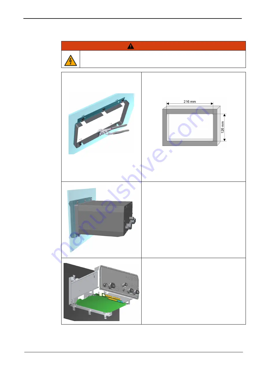
Figure 9 Panel mount bracket frame
1.
Cut an opening in the panel to accommodate
the bracket frame provided (this is the same
size as previous generations of ORBISPHERE
type 3600 instruments).
Figure 10 Opening dimensions
2.
Install the provided frame in the opening.
3.
Fold the 6 tabs over the panel lips, using
adjustable joint pliers.
4.
Slide the instrument in the bracket frame. The
instrument should go over the four “T” pins.
Rotate the 4 fast locking screws on both sides of
the front panel and slide it in.
5.
Rotate the 4 fast locking screws 1/4 turn twice in
the lock direction as indicated on the side of the
front panel. This locks the instrument in place on
the four “T” pins.
6.
To access the connections inside the
instrument, remove the instrument housing (six
screws on the back panel, and slide the housing
back out)
7.
Pass the cables through the housing, then
through the cable gland (if applicable) and then
perform the connections as detailed below.
Note:
Do not forget to pass the cable through the housing
before passing it through the cable gland on the back
panel.
Содержание ORBISPHERE K-M1100
Страница 1: ...DOC024 52 93023 ORBISPHERE Model K M1100 Sensor and Model 410 Analyzer USER MANUAL 01 2021 Edition 18 ...
Страница 5: ...4 Table of Contents ...
Страница 19: ...18 Specifications ...
Страница 39: ...38 Installation ...
Страница 45: ...44 User Interface ...
Страница 48: ...47 Section 6 View Menu Figure 33 View menu ...
Страница 51: ...50 View Menu ...
Страница 52: ...51 Section 7 Measurement Menu Figure 36 Measurement menu ...
Страница 59: ...58 Measurement Menu ...
Страница 65: ...64 Calibration Menu ...
Страница 66: ...65 Section 9 Inputs Outputs Menu Figure 39 Inputs Outputs menu ...
Страница 68: ...67 Inputs Outputs Menu 9 4 Analog outputs Figure 40 Analog outputs menu ...
Страница 75: ...74 Inputs Outputs Menu ...
Страница 91: ...90 Communication Menu ...
Страница 94: ...93 Section 12 Products Menu Figure 43 Products menu ...
Страница 97: ...96 Global Configuration Menu ...
Страница 98: ...97 Section 14 Services Menu Figure 45 Services menu part 1 ...
Страница 99: ...98 Services Menu Figure 46 Services menu part 2 ...
Страница 107: ...106 Maintenance and Troubleshooting ...
Страница 113: ...112 Accessories and Spare Parts ...


