background image

ES0609      rev D     4/09

10


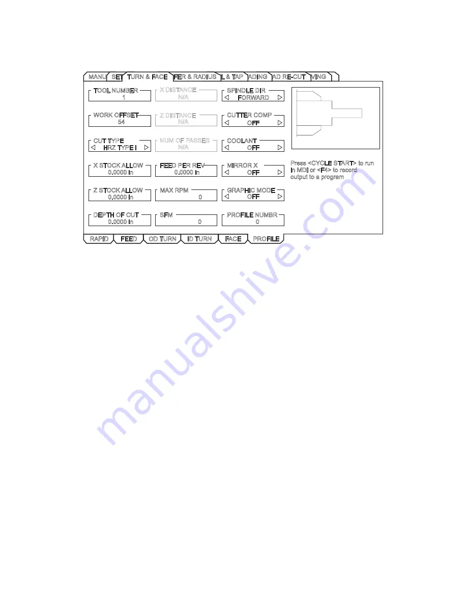
Turn & Face - Profile

This tab is only available if the machine has a control pendant with a 15” screen and  lathe software version 

8.04A or later.

RAPID

FEED

OD TURN

FACE

ID TURN

PROFILE

Press <CYCLE START> to run

in MDI or <F4> to record

output to a program

TOOL NUMBER

1

WORK OFFSET

54

CUT TYPE

HRZ TYPE I

X STOCK ALLOW

0.0000 in

NUM OF PASSES

X DISTANCE

Z DISTANCE

FEED PER REV

0.0000 in

SPINDLE DIR

CUTTER COMP

COOLANT

MIRROR X

Z STOCK ALLOW

0.0000 in

DEPTH OF CUT

0.0000 in

MAX RPM

0

SFM

0

GRAPHIC MODE

PROFILE NUMBR

0

FORWARD

OFF

OFF

OFF

OFF

N/A

N/A

N/A

GROOVING

THREAD RE-CUT

THREADING

DRILL & TAP

CHAMFER & RADIUS

MANUALSETUP

TURN & FACE

Tool Number

 – Enter the tool to be used.

Work Offset

 – Enter the work offset to be used.

Cut Type

 – Use the left/right cursor keys to select the type of cut (Horizontal, Vertical, Profile, Finish Fwd, Fin

-

ish Rev).

X Stock Allow

 – Enter the amount to leave on the diameter of the profile.

Z Stock Allow

 – Enter the amount to leave on the faces of the profile.

Depth of Cut

 – Enter the depth of cut for each pass of the stock removal.

Num of Passes

 – Enter the number of cutting passes. (Must be a positive number).

X Distance

 – Enter the X-axis distance and direction from first cut to last. (Radius value).

Z Distance

 – Enter the Z-axis distance and direction from first cut to last.

Feed Per Rev

 – Enter the feed per revolution.

MAX RPM

 – Enter the maximum spindle turning speed.

SFM

 – Enter the Surface Feed per Minute.

Spindle Dir 

– Use the left/right cursor keys to select spindle direction (Forward/Reverse). This depends on 

tool type.

Содержание TL Series

Страница 1: ...Haas Factory Outlet A Division of Productivity Inc Revised 06 2012 CNC Lathe Series Training Manual Haas TL Series Tool Room Lathe Operator ...

Страница 2: ...ntent must not be altered nor may the Productivity Inc name be removed from the materials This material is to be used as a guide to operation of the machine tool The Operator is responsible for following Safety Procedures as outlined by their instructor or manufacturer s specifications To obtain permission please contact trainingmn productivity com ...

Страница 3: ... DISPLAY KEYS 14 5 CURSOR KEYS 18 6 AND 7 ALPHA KEYS AND NUMERIC KEYS 18 8 MODE KEYS 20 SETTINGS 23 TOOL ROOM LATHE ORIENTATION AND WALK AROUND 24 POWER UP PROCEDURES 25 TOOL ROOM LATHE SAFETY 27 EMERGENCY STOP SWITCH 27 PROPER USE OF MACHINE GUARDING 28 DEAD MAN SWITCH 28 HAND WHEEL SAFETY 29 MAINTENANCE OF THE TL SERIES LATHE 30 HEADSTOCK LUBRICANT 31 GREASE POINTS 31 ALORIS TOOL POST OPERATION ...

Страница 4: ...YCLE MENU 50 GROOVE CUTTING CYCLE 51 THREAD CUTTING CYCLE 52 DRILL CYCLE 53 TAPPED HOLE CYCLE 54 SECTION II IPS WALK THROUGH FOR LATHES 59 SECTION III TL LIVE IMAGES FOR LATHES 99 For more information on Additional Training Opportunities or our Classroom Schedule Contact the Productivity Inc Applications Department in Minneapolis 763 476 8600 Visit us on the Web www productivity com Click on the T...

Страница 5: ...they are designed for manual semi manual and full CNC G M code operation Even though the TL series can be run from a G M code program Haas has equipped these unique machines with a unique control The Haas IPS Intuitive Programming System allows for quick and easy setup and programming of standard tool room style parts Since the TL series is so unique Productivity Inc had designed a specific class ...

Страница 6: ... zero to the left are negative increments The or positive increments are understood therefore no sign is needed We use positive and negative along with the increment s value to indicate its relationship to zero on the line In the case of the previous line if we choose to move to the third increment on the minus side of zero we would call for 3 If we choose the second increment in the plus range we...

Страница 7: ...at any point along each of the two number lines and in fact will probably be different for each setup of the machine It is noteworthy to mention that the X axis is set with the machine zero position on the center line of the spindle while the Z axis zero is set at the finished right of the part being machined This will place the entire X axis cutting in a positive range of travel whereas the Z axi...

Страница 8: ...is and somewhere on the Z axis we have automatically caused an intersection of the two lines This intersection where the two zeros come together will automatically have the four quadrants to its sides above and below it How much of a quadrant we will be able to access is determined by where we placed the zeros on the travel axes of the lathe ...

Страница 9: ...d the only way to move any of the two axes is in the negative direction This is because a new zero was set for each of the axes automatically when the machine was brought Home Machine home is placed at the edge of each axes travel Sometimes this point is referred to as Machine Zero as pointed out below Note the difference in the x coordinate system on a turret lathe and a table lathe Positive X is...

Страница 10: ...Productivity Inc Haas CNC TL Series Lathe Operator Manual Page 8 Cartesian Coordinate Exercise POINT X Position Z Position P1 X 5 0 Z 0 P2 P3 P4 P5 P6 P7 P8 P9 P10 ...

Страница 11: ...s to machine zero and then indexes the turret to tool Machine will move up in X first to machine zero and then the Z move to machine zero If the correct program has been selected and the part program is proven to be good and it s ready to run press cycle start General Machine Keys Power On Turns CNC machine on Power Off Turns CNC machine tool off Emergency Stop Stops all axis motion stops spindle ...

Страница 12: ...JOG keys Provides all control features for machine setup Edit EDIT MDI DNC LIST PROG keys Provides all program editing management and transfer functions Operation MEM key Provides all control features necessary to make a part Current mode is displayed at top of display Functions from another mode can still be accessed within the active mode For example while in the Operation mode pressing OFFSET w...

Страница 13: ...eys Jog Keys Override Keys Display Keys Cursor Keys Alpha Keys Number Keys and Mode Keys In addition there are miscellaneous keys and features located on the pendant and keyboard which are described briefly on the following pages 1 Function Keys 2 Jog Keys 3 Override 5 Cursor Keys 4 Display Keys 6 Alpha Keys 7 Number Keys 8 Mode Keys HAAS LATHE SERIES ...

Страница 14: ...s jog modes during a set up Z FACE MEASURE Used to record Z tool offsets and Z work offsets 2 Jog Keys Chip FWD Chip Conveyer Forward Turns the chip conveyer in a direction that removes chips from the work cell Chip STOP Chip Auger Stop Stops chip conveyer movement Chip REV Chip Auger Reverse Turns the chip conveyer in reverse TS Moves tailstock toward the spindle TS Rapid Increases speed of tails...

Страница 15: ...se direction STOP Stops the spindle CCW Starts the spindle in the counterclockwise direction 5 RAPID Limits rapid moves to 5 percent of maximum 25 RAPID Limits rapid moves to 25 percent of maximum 50 RAPID Limits rapid moves to 50 percent of maximum 100 RAPID Allows rapid traverse to feed at its maximum Override Usage Feed rates may be varied from 0 to 999 Feed rate override is ineffective during ...

Страница 16: ...chine zero the location that the machine moves to automatically when you press POWER UP RESTART This display will show the current distance from machine zero 4 POS TO GO digital display When you re running the machine or when you have the machine in a Feed Hold this incrementally displays the travel distance remaining in the active program block being run This is useful information when you are st...

Страница 17: ...he tool has reached maximum load the machine will stop and alarm out for you to check the condition of that tool Pressing ORIGIN will clear the cursor selected display and pressing ORIGIN when the cursor is at the top of a column will clear the whole column Setting 84 determines the Overload Action when this limit is met Also vibration loads may be entered 8 Maintenance times for various items may...

Страница 18: ...ions made in the Settings display on the page titled GRAPHICS 1 Press either MEM or MDI and select the program that you want to run in Graphics Graphics will also run in the Edit Mode 2 Press SETNG GRAPH twice The top left line of the screen will list the GRAPHICS title Above that line will list the mode you are in MEM or MDI The bottom lists explanations for use of function keys F1 through F4 The...

Страница 19: ... all tabs It also will solve trig problems with information about triangles circles circle line tangent and circle circle tangent A milling and tapping tab will give you suggested cutting speeds and feeds per different materials and sized tools Simple Calculator It will calculate simple addition subtraction multiplication and division operations Operations are listed as LOAD These are selected usi...

Страница 20: ... Input Section of the control lower left hand corner SHIFT key provides access to the yellow characters shown in the upper left corner of some of the alphanumeric buttons on the keyboard Pressing SHIFT and then the desired white character key will enter that character into the input buffer EOB key enters the end of block character which is displayed as a semicolon on the screen and signifies the e...

Страница 21: ...acter put into the Input Section of the control display Space Is used to format comments placed into the Input Section of the control display Write Enter General purpose Enter key It inserts code from the input section into a program when the program display is in EDIT mode With offsets pages active pressing the WRITE ENTER key adds a number in the Input Section to the highlighted cell Pressing th...

Страница 22: ...SERT Enters commands keyed into the input panel in lower left pane of CRT after the cursor highlighted word in a program ALTER Highlighted words are replaced by text input into the input panel DELETE Highlighted words are deleted from a program UNDO Will undo up to the last 9 edit changes F1 KEY While in the edit mode pressing F1 will bring up an edit pop up window Using the sideways cursor button...

Страница 23: ...op at any M01 which is in the program Normally M01s are placed after a tool is run in a program When a job is being set up the operator may put machine in op stop mode to check dimensions after every tool has completed cutting BLOCK DELETE When this button is depressed any block with a slash in it is ignored of skipped MDI DNC MANUAL DATA INPUT mode Usually short programs are written in MDI but ar...

Страница 24: ...M or USB Cursor to left or right for which list one wants Pressing Enter will open a list of programs Cursor UP Ù or DOWN Ú to program desired Select the desired programs to be moved by pressing WRITE ENTER This will put a check mark beside it F2 will copy selected program or programs to be moved A pop up menu will ask where you want the selected programs to be copied SELECT PROG After highlightin...

Страница 25: ...s versions the jog handle could only be used to scroll through cursor highlight the parameters but not the settings This has been corrected Any Mill Control Ver 10 15 and above any Lathe Control Ver 3 05 and above There are many settings which give the user various options over the control of their machine tool Read the Settings section of the operator s manual for all the possible options ...

Страница 26: ...k Around The agenda for this section of the training manual is to familiarize everyone with the physical layout of the TL series machine the functions of the mechanical features of the machine and general maintenance of the TL series lathe FRONT VIEW OF TL SERIES LATHE TOP DOWN VIEW OF TL SERIES LATHE ...

Страница 27: ...ock if equipped all the way to the far right of the limits of the machine and leave the clamps on the tailstock loose This will provide the saddle enough room to reference itself CAUTION the control does not know where the tailstock is and there is a chance to crash if the tailstock is not in the home position 2 Visually verify that all of the machine s ways are clean and free of dirt and any movi...

Страница 28: ...chine to it s farthest most limits so that the cross slide and saddle can be detected by the limit switches 1 Locate the orange RESET key and push it to clear any alarms that are present and to power on the servos of the machine 2 Next to the RESET button is the POWER UP RESTART button Press it once and the machine will travel the X axis first then the Z axis to their utmost farthest limits which ...

Страница 29: ... with a yellow ring This is the EMERGENCY STOP or E STOP button In the event of a un controlled machine condition a crash of the machine or any situation that requires an immediate shut down of all axis functions movement spindle functions and power to the servos of the machine the Emergency Stop button should be used This button is used to halt everything on the machine immediately Emergency Stop...

Страница 30: ...surrounds the chuck or a complete set of sheet metal that encloses the machine and the machine should not be run with any guards open In the current version of the TL series of software it is impossible to run in either manual or CNC modes with the guarding open The setting on the control may be changed but changing this setting rests all responsibility on the operator and or the owner s of the ma...

Страница 31: ...eries of lathes when in CNC mode will still move the manual handwheels as the machine moves PLEASE PAY ATTENTION TO THE HANDWHEELS TO AVOID ANY INJURY Even though elaborate thought has been put into making sure the TL series is safe extra caution needs to been given to any moving part of the machine ...

Страница 32: ...parts filters and lubricants that are as specified to insure longevity of the life of your or your boss s investment This will maintain the highest levels of performance and accuracies for the longest possible time If there is any question on what exactly to use please refer to the Operator s Manual for these specifications or contact the Productivity Service and Parts Department for the proper fl...

Страница 33: ... The linear ways the ballscrews and the tailstock are all equipped with grease fittings and they should be lubricated weekly to insure consistent performance and accuracy of your machine TL Series Lubrication Points 1 X axis cross slide trucks 2 X axis cross slide ball screw 3 Z axis saddle trucks 4 Tail stock screw 5 Z axis saddle ball screw 6 Tailstock base four places For the lubrication points...

Страница 34: ...ons to allow for safe holding of a wide variety of different tooling products Aloris Super Precision Tool Post All that is required of the operator to switch from one tool to the next is to swing the handle in a counter clockwise direction to release the current tool pull the tool holder up and off of the Aloris dovetail slide on the next tool onto the Aloris dovetail and swing the lever till cloc...

Страница 35: ...the chuck center and counter clockwise to move the jaws away from the chuck center The configuration of the chuck jaws and part holding is up to the operator to decide which is best for that particular project 3 Jaw Scroll Chuck Key CAUTION The chuck key comes equipped with a spring on the end to prevent accidentally starting the spindle with the chuck key engaged to the chuck DO NOT REMOVE THE SP...

Страница 36: ...hine and allows the operator to program using a question and answer format rather than a G M code format The objective of this section is to go thru the different IPS system Tabs and Menus and how each relates to generating fast and accurate parts from the TL Series Lathe The best way to do this from a training point of view is to start with a typical part print that would be seen by a Toolroom La...

Страница 37: ...ppears The cursor keys at the middle of the Haas control navigate thru the different TABS from left to right Pressing the WRITE ENTER key will access the selected tab If there are multiple choices under each tab again use the right and left cursor control to navigate in the SUB TABS to select the cycle you want to program At any time pressing the CANCEL button will back out of any SUB TAB or TAB ...

Страница 38: ...ND JOG key and pressing the yellow shift key in conjunction with either the Z Z or X X or both jog keys In this mode Tool Geometry may be set by establishing a part Z zero by facing the part off manually The spindle is commanded on by entering a value for the spindle speed and pressing either the FWD or REV buttons The spindle speed override keys 10 can be used to adjust the commanded speed from t...

Страница 39: ... to the face or turning position manually Next a DELTA X or a DELTA Z distance selected A feed and spindle speed is entered The delta x or delta z values are the incremental distance machine will move at the prescribed feed and speed from the present position it is at Pressing the F4 key then selecting Output to MDI will create the program into MDI With a DELTA X of 3 0 entered the following short...

Страница 40: ...Productivity Inc Haas CNC TL Series Lathe Operator Manual Page 38 TL Series Training Part ...

Страница 41: ...and what tools will be needed for each operation For our part that is drawn above we need have the following processes that need to be done 1 Turn the 2 750 Dia 2 Turn the 1 750 Dia 3 Face the end of the part 4 Turn the 08x 08 chamfer 5 Turn the 250 Radius 6 Groove the back of the thread 7 Turn the 1 75x10 thread 8 Drill the 20 tapped hole 9 Tap the 20 tapped hole Processes 1 5 can be performed wi...

Страница 42: ...Process 7 is our OD Thread and needs to be performed with an OD Threading tool like this We will call this Tool 3 For Process 8 we need to drill the hole for our tap a 201 Dia drill like this Tool 4 And for Process 9 we will tap our hole with a 20 tap like this Tool 5 ...

Страница 43: ...etween tools 1 20 depending on the version of software your TL series has Each tool will have the same information listed After selecting the tool it must be made active by pressing the NEXT TOOL key The active tool will be displayed in the lower right hand corner of the control display Arrow down to Tool Type and select the correct designation by using right and left cursor keys Enter the OFFSET ...

Страница 44: ...tomatically write the X Offset into the X offset box Next handwheel the machine over and touch Tool 1 to the face of our part using the feeler gauge and simply press the Z FACE MEASURE key This will automatically store the Z Offset for that tool All that is left to do is enter the tool nose radius for that insert and define the Tool Tip Type or in simpler terms which direction the tool is pointing...

Страница 45: ... into the chuck and align the drill so that the flute tips of the drill are horizontal to the cross slide of the machine Simply handwheel the drill over to the diameter of our stock and use a feeler gauge pick up the edge of the part Press the X DIAM MEASURE key and again the control will ask for our diameter but since we need to compensate for our radius of our drill ADD 201 to the diameter of th...

Страница 46: ...acing operations for the IPS are located under the TURN FACE main tab so back out to the main tab selection view and use the right or left cursor keys to highlight the TURN FACE tab Press WRITE ENTER to access the TURN FACE mode then select OD TURN to start our processes 1 2 The display below will appear ...

Страница 47: ...n Surface Footage Recommended Insert SFM Max Spindle Speed Max RPM Of Spindle For The Cycle For the 1st process our 2 500 Diameter we will enter the answers below IPS OD Cycle Question Relationship To The Part Tool Number 1 Part Offset G54 Start Diameter 3 000 Finish Diameter 2 500 Depth Of Cut 100 Z Dimension 2 25 Feed Per Revolution 011 Surface Footage 350 Max Spindle Speed 1500 Once all the var...

Страница 48: ...t the program created may be recorded into a new program or added to a program in memory Press the F4 key and the IPS RECORDER pop up screen will appear Cursor key to option 1 press enter and a new program may be created or an old one selected Option 2 will record program to current program in the active memory For this example program O1 was created ...

Страница 49: ...indle Speed Face Cutting Cycle The face cutting cycle is similar to the OD Cycle it just roughs and finishes across the end of the part then the OD Enter the variables to face the end of our part IPS Face Cycle Question Relationship To The Part Tool Number Part Offset Start Diameter Finish Diameter Depth Of Cut Z Dimension Feed Per Revolution Surface Footage Max Spindle Speed Since on the first pa...

Страница 50: ... of the threads Press CANCEL till we get back to the MAIN TABS screen use the RIGHT or LEFT CURSORS to move to the OD CHAMFER menu below Fill out the details that are needed for the chamfer IPS Chamfer Cycle Question Relationship To The Part Tool Number Part Offset X Diameter Length Depth Of Cut Z Dimension Feed Per Revolution Surface Footage Max Spindle Speed ...

Страница 51: ...Productivity Inc Haas CNC TL Series Lathe Operator Manual Page 49 The variables are entered into the IPS chamfer menu This code will be created and recorded at the end of O1 ...

Страница 52: ...e control and its pictures Operation 5 is to turn the 250 radius on the 2 500 diameter Navigate to the OD RADIUS Tab and enter the information needed below IPS OD Radius Cycle Question Relationship To The Part Tool Number Part Offset X Diameter Radius Depth Of Cut Z Start Feed Per Revolution Surface Footage Max Spindle Speed Add the code created from above to the end of Program O1 ...

Страница 53: ...t OD GROOVE to do process 6 Input the information the IPS is asking for verify it cuts a good part then use the recorder again to record this feature IPS OD Groove Cycle Question Relationship To The Part Tool Number Part Offset X Start Diameter Z Face Diam To Cut Groove Width Grooving Tool Width Feed Per Revolution Surface Footage Max Spindle Speed ...

Страница 54: ...stions the menu asks for IPS OD Thread Cycle Question Relationship To The Part Tool Number Part Offset X Start Diameter Z Face Thread Length Minor Diam Major Diam TPI Depth Of Cut Spindle RPM Input the answers into the threading cycle and run the cycle to make sure we have a good thread Once we are to size RECORD the thread cycle with the IPS recorder CAUTION Once the control has started a pass of...

Страница 55: ...o so and have an automatic drilling with pecks Go to the DRILL TAP menu and select PECK DRILLING and we will get the menu below For peck drilling just simply enter the values listed below cycle the menu to make sure we get the correct depth and then record it with IPS IPS Peck Drilling Cycle Question Relationship To The Part Tool Number Part Offset X Centerline Z Face Depth Spindle RPM Feed Per Re...

Страница 56: ...se at the bottom of the hole and back the tap out automatically IPS RH Tap Cycle Question Relationship to the Part Tool Number Part Offset X Centerline Z Face Depth Spindle RPM TPI Once we have recorded all of our features of our part we will have one complete program for the part If we want to run another part just like it select O1 and Cycle Start We will have to press cycle start between every ...

Страница 57: ... will accept any standard ISO G M code program and will understand the code but if you are interested in learning more about G M code programming please contact Productivity Inc and sign up for our Lathe Programming class The TL Series is built around the IPS system and is designed to take advantage of it and thus the only reason we teach only the IPS for it s operation Before running a complete p...

Страница 58: ... G72 P101 Q102 U0 W0 D0 035 F0 006 N101 G00 Z0 G01 X0 N102 G01 X0 Z0 05 G00 X3 Z0 M01 OD TURN 2 5 DIAM T101 G54 G50 S1500 G96 S350 M03 G00 X3 075 G00 Z0 05 G71 P101 Q102 U0 W0 D0 1 F0 011 N101 G00 X2 5 G01 X2 5 Z 2 25 N102 G01 X3 075 G00 X3 075 Z0 05 M01 OD TURN 1 75 T101 G54 G50 S1500 G96 S350 M03 G00 X2 575 G00 Z0 05 G71 P101 Q102 U0 W0 D0 1 F0 011 N101 G00 X1 75 G01 X1 75 Z 1 5 N102 G01 X2 575 ...

Страница 59: ...01 X1 75 Z 0 1115 G00 X1 75 Z0 M01 OD RADIUS T101 G54 G50 S1000 G96 S300 M03 G00 X2 55 Z 1 45 G71 P101 Q102 U0 W0 D0 05 F0 006 N101 G00 X1 938 G01 Z 1 5 N102 G03 X2 5 Z 1 781 R0 281 G00 X2 55 Z 1 45 M01 OD GROOVE T202 G54 G50 S1000 G96 S200 M03 G00 X1 855 G00 Z0 05 G00 X1 855 Z 1 501 G75 X1 555 Z 1 498 K0 189 F0 002 G00 X1 855 G00 Z 1 499 G01 X1 55 F0 002 G01 Z 1 5 G01 X1 855 G00 Z0 05 M01 ...

Страница 60: ...T303 G54 G97 S1000 M03 G00 X1 8416 Z0 5 G04 P1 M09 M24 G76 X1 6291 Z 1 45 K0 0763 I0 D0 0169 F0 1 G00 X1 8416 Z0 5 M09 M01 PECK DRILL T404 G54 G97 S1000 M03 G00 X0 Z0 1 G83 X0 Z 1 5 Q0 2 F0 002 G80 G00 Z0 1 M01 TAP T505 G54 G97 S350 G00 X0 Z0 2 G84 X0 Z 1 R0 2 F0 05 G80 M01 M30 ...

Страница 61: ...Productivity Inc Haas CNC TL Series Lathe Operator Manual Page 59 Section II IPS Walk Through for Lathes Haas ES Doc ES0609 ...

Страница 62: ......

Страница 63: ...ES0609 rev D 4 09 1 Intuitive Programming System Walk Through For Lathes ...

Страница 64: ...gh the Toolroom Lathe screens is also accessible by going to full CNC MDI mode The program can be edited and saved from the full CNC mode NOTE The IPS menu is displayed at power up and is available in the following configurations 10 LCD and software version 7 xx and earlier IPS 15 LCD and software version 8 03 and earlier IPS upgradable to Profile Creator 15 LCD and software version 8 04A and late...

Страница 65: ... of the hold to run switch pressing Reset or the pressing the Stop button Setup Stock Setup GROOVING GROOVING THREAD RE CUT THREADING DRILL TAP CHAMFER RADIUS TURN FACE MANUAL SETUP STOCK TOOL WORK TAILSTOCK STOCK DIA STOCK LENGTH STOCK FACE 0 1000 in HOLE SIZE 0 0000 in JAW THICKNESS 2 0000 in 2 0000 in 1 5000 in CLAMP STOCK JAW HEIGHT STEP HEIGHT 3 0000 in 3 0000 in 0 5000 in STOCK JAWS BAR FEED...

Страница 66: ...rrent tool number Use the turret FWD REV or the Next Tool buttons to set up another tool Tool Type Right Left arrows select among 16 tool types Drill Tap Vert Tap Vert Drill End Mill V End Mill Ballnose V Ballnose OD Turn ID Bore OD Groove ID Groove Face Groove OD Thread ID Thread and Cut Off Offset Num X Offset The X axis offset for the current tool Press X Dia Meas to record this position X Wear...

Страница 67: ...rite to add the value to the current value or F1 to replace the value with the entered value Press Part Zero Set to record the Z Offset current position Tailstock Setup STOCK TOOL WORK TAILSTOCK LIVE CTR ANG 60 000 deg DIAMETER LENGTH 2 0000 in TS POSITION TS OFFSET RETRACT DIST 0 0000 in X CLEARANCE Z CLEARANCE ADVANCE DIST 0 0000 in 0 0000 in 1 2500 in NOT MODIFIABLE TS HOLD POINT is the sum of ...

Страница 68: ...RANCE sets clearance to max travel Z Clearance Minimum allowable difference between the Z axis and the tail stock A value of 1 0000 means that when the X axis is below the X clearance plane the Z axis must be more than 1 inch away from the tail stock position in the Z axis negative direction The default value for this setting is zero Press Write to add F1 to set or Part Zero Set to record current ...

Страница 69: ...0000 in DELTA Z 0 0000 in FEED PER REV 0 0000 in SPINDLE RPM 0 0000 in Press CYCLE START to run in MDI or F4 to record output to a program GROOVING THREAD RE CUT THREADING DRILL TAP CHAMFER RADIUS MANUAL SETUP TURN FACE Tool Number Enter the tool to be used Work Offset Enter the work offset to be used Delta X Enter the X coordinate of the end point of the linear motion desired Delta Z Enter the Z ...

Страница 70: ...the finished diameter Z Dimension Enter the Z axis dimension of the part from the Z start point Depth of Cut Enter the depth of cut for each pass of the stock removal Feed Per Rev Enter the feed per revolution MAX RPM Enter the maximum spindle turning speed SFM Enter the Surface Feed per Minute Fillet Radii Enter the corner fillet radii or enter 0 for none Tool Nose Enter the tool nose radius Turn...

Страница 71: ...cord output to a program TOOL NUMBER 1 WORK OFFSET 54 OUTSIDE DIA 0 0000 in DIA TO CUT 0 0000 in Z DIMENSION DEPTH OF CUT 0 0350 in FEED PER REV 0 0060 in MAX RPM 1000 SFM 200 0 0000 in GROOVING THREAD RE CUT THREADING DRILL TAP CHAMFER RADIUS MANUAL SETUP TURN FACE Tool Number Enter the tool to be used Work Offset Enter the work offset to be used Outside Dia Enter the current diameter of the work...

Страница 72: ... the tool to be used Work Offset Enter the work offset to be used Cut Type Use the left right cursor keys to select the type of cut Horizontal Vertical Profile Finish Fwd Fin ish Rev X Stock Allow Enter the amount to leave on the diameter of the profile Z Stock Allow Enter the amount to leave on the faces of the profile Depth of Cut Enter the depth of cut for each pass of the stock removal Num of ...

Страница 73: ...t Type to Horizontal set X Stock Allow to 0 02 set Z Stock Allow to 0 005 set Depth of Cut to 0 075 set Feed per Rev to 0 01 set Max RPM to 1500 set SFM to 350 set Graphic Mode to ON and Profile Number to 1 7 Select the Profile Number data box and press Write Enter or press F1 when in the Profile tab A Profile Selector popup window is displayed The Profile Selector popup is used to select a profil...

Страница 74: ...s move the part around on the screen 0001 001 01 1 Changes the jog step size while drawing in the graphic window To Build the Profile Shown a Select the Rapd Pt row Use the arrow keys to select the X POS column and enter 3 5 Use the arrow keys to select the Z POS column and enter 0 1 Use the arrow keys to go to the beginning of the Start row b Leave the Start PT at X0 Z0 Use the arrow keys to go t...

Страница 75: ...selected Jog Z to 1 5 and press Write Enter Use the cursor keys to go back to the previous line and select the Radius column Enter 0 25 press Write Enter and use the cursor keys to come back to this line Go to the beginning of the next line Press 1 to activate a Feed move h Press Write Enter until X POS is selected Jog X to 3 0 Press Write Enter until Z POS is selected Jog Z to 2 0 and press Write...

Страница 76: ...mory If Graphic Mode is set to ON in the Turn Face Profile screen when Cycle Start is pressed to run a profile a graphic screen is displayed showing the graphical representation of the profile Graphic Mode To cut the profile on the other side of the workpiece set Mirror X to ON in Turn Face Profile screen it is not necessary to change Mirror X in Settings When Cycle Start is pressed the opposite s...

Страница 77: ... Profile Activate Zoom ZOOM HELP Zoom In Zoom Out Scroll Up Scroll Down Scroll Right Scroll Left Exit Zoom DATA TABLE HELP Enter Data Into Table Insert Line Into Table Clear All Data In Table Go To X Axis Data Box Go To Z Axis Data Box Move Up To Next Data Box Move Down To Next Data Box Move Right To Next Data Box Move Left To Next Data Box F2 F3 F4 PAGE UP PAGE DOWN UP CURSOR KEY DOWN CURSOR KEY ...

Страница 78: ...Move Down To Next Data Box Moves down to next data box below its current location Will not move if already at the bottom of the table Move Right To Next Data Box Moves to the next data box to the right of its current location Will wrap if already at the far right Move Left To Next Data Box Moves to the next data box to the left of its current location Will wrap if already at the far left Chamfer R...

Страница 79: ...he selected tool Normally this information is included with the tool SFM Enter the Surface Feed per Minute Advanced Users In the full CNC mode this is a G71 command Chamfer Radius I D Radius This mode is used to cut an inside diameter radius Press CYCLE START to run in MDI or F4 to record output to a program OD RADIUS ID RADIUS OD CHAMFER ID CHAMFER TOOL NUMBER 1 WORK OFFSET 54 Z START PT 0 0000 i...

Страница 80: ...us of the selected tool Normally this information is included with the tool SFM Enter the Surface Feed per Minute Advanced Users In the full CNC mode this is a G71 command Chamfer Radius OD Chamfer This mode is used to cut an outside diameter chamfer Press CYCLE START to run in MDI or F4 to record output to a program OD RADIUS ID RADIUS OD CHAMFER ID CHAMFER TOOL NUMBER 1 WORK OFFSET 54 Z START PT...

Страница 81: ... Radius ID Chamfer This mode is used to cut an outside diameter chamfer Press CYCLE START to run in MDI or F4 to record output to a program OD RADIUS ID RADIUS OD CHAMFER ID CHAMFER TOOL NUMBER 1 WORK OFFSET 54 Z START PT 0 0000 in INSIDE DIA 0 0000 in CHAMFER 0 0000 in 0 000 deg 0 0400 in FEED PER REV 0 0060 in TOOL NOSE 0 0315 in ANGLE DEPTH OF CUT MAX RPM 1000 200 SFM GROOVING THREAD RE CUT THR...

Страница 82: ... Advanced Users In the full CNC mode this is a G71 command Drill Tap Drill This mode is a drill cycle that can pause at the bottom of the hole GROOVING THREAD RE CUT THREADING MANUAL SETUP TURN FACE Press CYCLE START to run in MDI or F4 to record output to a program DRILL PECK DRILL TAP REVERSE TAP CHAMFER RADIUS TOOL NUMBER 1 WORK OFFSET 54 Z START PT 0 0000 in DEPTH OF HOLE 0 0000 in 0 0030 in 0...

Страница 83: ...n 0 0000 in 0 0000 sec PECK DISTANCE SPINDLE RPM FEED PER REV 1000 GROOVING THREAD RE CUT THREADING MANUAL SETUP TURN FACE CHAMFER RADIUS DRILL TAP Tool Number Enter the tool to be used Work Offset Enter the work offset to be used Z Start Pt Enter the Z axis starting point Depth of Hole Enter the depth to drill Entered value must be positive Peck Distance Enter the length of each peck before retra...

Страница 84: ...l to be used Work Offset Enter the work offset to be used Z Start PT Enter the Z axis starting point Tap Depth Enhter the depth to tap Entered value must be positive TPI Threads per Inch Enter the number of Threads per Inch This is how many threads to cut per inch Spindle RPM Enter spindle RPM commanded spindle speed Spindle speed should not exceed 500 RPM Advanced Users In the full CNC mode this ...

Страница 85: ...ed Users In the full CNC mode this is a G184 command Rigid Tapping Option needed Threading OD Thread This mode is used for cutting outside diameter threads using multiple passes GROOVING THREAD RE CUT MANUAL SETUP TURN FACE Press CYCLE START to run in MDI or F4 to record output to a program CHAMFER RADIUS DRILL TAP TOOL NUMBER 1 WORK OFFSET 54 Z START PT 0 0000 in THREAD LENGTH 0 0000 in OD THREAD...

Страница 86: ...g inside diameter threads using multiple passes Press CYCLE START to run in MDI or F4 to record output to a program TOOL NUMBER 1 WORK OFFSET 54 Z START PT 0 0000 in THREAD LENGTH 0 0000 in OD THREAD ID THREAD OD THREAD REPAIR ID THREAD REPAIR MINOR 0 0000 in 0 0000 in 0 000 DEPTH OF CUT 0 0150 in TAPER 0 0000 in MAJOR TPI SPINDLE RPM 1000 RIGHT CHAMFER OFF THREAD DIR COOLANT OFF GROOVING THREAD R...

Страница 87: ... 0000 in 0 0000 in GROOVING THREAD RE CUT MANUAL SETUP TURN FACE CHAMFER RADIUS DRILL TAP THREADING Reference Jog the tool into the threads then press the X DIA MEAS key 1 reference point recorded TPI Enter the number of Threads per Inch or Threads per Millimeter Thread Height TL Clearance No Of Threads Enter the number of threads from the tool to the end of the part Thread Length Enter the length...

Страница 88: ... Inch or Threads per Millimeter Thread Height TL Clearance No Of Threads Enter the number of threads from the tool to the end of the part Thread Length Enter the length of the threaded portion of the part Threads to Clear Depth of cut Enter the amount of stock to be removed on each pass Spindle RPM Enter the spindle RPM Taper Enter a positive value for thread taper per ft X Offset Enter a value on...

Страница 89: ... in ORIENT RPM 10 CHAMFER RADIUS DRILL TAP THREADING THREAD RE CUT 0 0000 in Work Offset Z Offset Program Number X Clearance Z Clearance Orient RPM Thread Re Cut Thread Teach Position Step 2 of 3 This mode is used to position the OD or ID thread tool to a specific diameter by a Z minus position based on thread pitch SET OFFSET PUSH BACK THREAD TEACH POSITION SET REFERENCE RE CUT TOOL NUMBER G54 WO...

Страница 90: ...ET OFFSET PUSH BACK THREAD TEACH POSITION SET REFERENCE RE CUT REFERENCE 0 PGM NUMBER X CLEARANCE Z CLEARANCE STEP 3 OF 3 X TOOL WEAR 0 0000 in Z OFFSET NOT SET 0 0000 in ORIENT RPM 10 0 0000 in 0 0000 in GROOVING MANUAL SETUP TURN FACE CHAMFER RADIUS DRILL TAP THREADING THREAD RE CUT Reference Program Number X Clearance Z Clearance X Tool Wear Z Offset Orient RPM Grooving Mode OD Groove This mode...

Страница 91: ...the current diameter of the work piece Manually measure the diameter Dia to Cut Diameter to Cut Enter the finished diameter Z Dimension Enter the Z axis dimension of the groove Entered value must be positive Groove Width Enter the finished width of the groove Entered value must be positive Tool Width Enter the actual width of the tool Feed per Rev Enter the feed per revolution MAX RPM Enter the ma...

Страница 92: ...a Enter the current diameter of the work piece Manually measure the diameter Dia to Cut Diameter to Cut Enter the finished diameter Z Dimension Enter the Z axis dimension of the groove Entered value must be positive Groove Width Enter the finished width of the groove Entered value must be positive Tool Width Enter the actual width of the tool Feed per Rev Enter the feed per revolution MAX RPM Ente...

Страница 93: ...er of the part This is the current diameter of the workpiece Manually measure the diameter Dia to Cut Diameter to Cut Enter the depth the tool is to cut into the part NOTE Entering a negative value for Dia to Cut causes the tool to pass spindle center and machine the entire face of the part Do Not enter a value larger than 100 Part Length Enter the finished part length Entered value must be positi...

Страница 94: ...ctual diameter of the part This is the current diameter of the workpiece Manually measure the diameter Dia to Cut Diameter to Cut Enter the depth the tool is to cut into the part NOTE Entering a negative value for Dia to Cut causes the tool to pass spindle center and machine the entire face of the part Do Not enter a value larger than 100 Part Length Enter the finished part length Entered value mu...

Страница 95: ...rt it into the editor Exit F1 Zoom ON OFF F4 Prev Chain pt LEFT Next Chain pt RIGHT Select Point UP DOWN Cancel Action CANCEL Select Group PG UP DN Chng Line Width ALTER Delete Group DELETE Undo Group UNDO X 0 0000 Z 0 0000 Type START Group 0 Chain 0 EXTRA KEY COMMANDS Enter Origin Point Use one of the following and press the WRITE key X 0 0000 1 Jog to X and Z position on part Use jog axis keys Z...

Страница 96: ... start of the tool path Press F2 to display a CHAIN OPTIONS pop up screen Chain Group This step finds the geometry of the shape s The auto chaining function will find most part geometry If the geometry branches off a pop up will prompt you to select a branch and automatic chaining will continue The Automatic Chaining function is typically the best choice as it will automatically plot the tool path...

Страница 97: ...v Chain pt LEFT Next Chain pt RIGHT Select Point UP DOWN Cancel Action CANCEL Select Group PG UP DN Chng Line Width ALTER Delete Group DELETE Undo Group UNDO Type Group Chain START 1 1 EXTRA KEY COMMANDS EDIT EDIT Enter the number of the profile to use press ENTER to open shape select or press F1 key Press to go back to the DXF editor EDIT X 9 1112 Z 6 1388 CURRENT GROUPS Group 1 PROFILE OD GROOVI...

Страница 98: ...n 0 0000 in FEED OD TURN ID TURN FACE PROFILE 3 Press F4 to access the IPS recorder menu Choose menu option 1 or 2 to continue or option 3 to cancel and return to IPS F4 can also be used to return to IPS from any point within IPS recorder IPS Recorder Menu Menu Option 1 Select Create Program Select this menu option to choose an existing program in memory or to create a new program into which the G...

Страница 99: ...n point for the new code Press WRITE to insert the code Menu Option 2 Output to Current Program 1 Select this option to open the currently selected program in memory 2 Use the arrow keys to move the cursor to the desired insertion point for the new code Press WRITE to insert the code ...

Страница 100: ...IP CHIP TS TS TS RAPID STOP FWD REV 7 8 9 4 1 CANCEL 5 2 0 SPACE 6 3 WRITE ENTER SHIFT E D C B A K Q W J P V I O U EOB H N T Z G M S Y F L R X 10 100 10 FWD STOP REV FEED RATE FEED RATE FEED RATE 10 100 10 SPINDLE SPINDLE SPINDLE RAPID 5 RAPID RAPID RAPID 25 50 100 INSERT ALTER DELETE UNDO SINGLE DRY OPTION BLOCK BLOCK RUN STOP DELETE COOLNT JOG TURRET TURRET FWD REV 0001 001 01 1 1 1 10 100 ALL O...

Страница 101: ...Productivity Inc Haas CNC TL Series Lathe Operator Manual Page 99 Section III TL Live Images for Lathes Haas ES Doc ES0666 ...

Страница 102: ......

Страница 103: ...Stock Setup screen VQC SETUP STOCK TOOL WORK STOCK DIA STOCK LENGTH 6 0000 in JAW THKNS JAW HEIGHT 3 5000 in STOCK FACE 0 0500 in HOLE SIZE STEP HEIGHT 2 0000 in CLAMP STOCK 0 2500 in STOCK JAWS 6 0000 in 1 5000 in 0 0000 in TAILSTOCK STOCK ORIENT MN SPINDLE STOCK ORIENT RAPID PT N A CLAMPING PT N A MACHINE PT N A Navigate screens using the left right up down arrow keys to select fields To enter t...

Страница 104: ... LIVE CENTER ANGLE 221 TAILSTOCK DIAMETER 222 TAILSTOCK LENGTH GENERALPROGRAMI O LIVE IMAGE POWER SETTINGS MAINTENANCE SYSTEM CONTROL PANEL LIVE IMAGE 1 1050 0 0000 0 0000 0 0000 0 0500 6 5000 6 0000 3 5000 2 5000 0 2500 2 0000 OFF OFF ON OFF OFF OFF OFF OFF Settings 202 Live Image Scale Height Specifies the height of the work area that is displayed in the live image screen The maximum size is aut...

Страница 105: ...rols the diameter of the tailstock Used to display the tailstock in live image 222 Tailstock Length Controls the length of the tailstock Used to display the tailstock in live image 224 Flip Part Stock Diameter Controls the new diameter location of the jaws after flipping the part 225 Flip Part Stock Length Controls the new length location of the jaws after flipping the part 226 SS Stock Diameter C...

Страница 106: ...in 0 0000 in VQC SETUP Selected Tool 9 Active Tool 9 STOCK TOOL WORK X WEAR 0 0000 in Z OFFSET 11 0000 in TOOL LENGTH 6 5000 in STEP HEIGHT 4 0000 in FROM CENTER DIAMETER 1 2500 in 0 0000 in 0 1250 in 9 N A N A Press TURRET FWD or TURRET REV to change the selected tool Press NEXT TOOL to make selected tool active TAILSTOCK NOTE Tool offset data may be entered for up to 50 tools The following secti...

Страница 107: ...ES0666 rev D 09 09 5 Sample Tool Setup Screens ...

Страница 108: ...FFSET and is stored in setting 107 TAILSTOCK 10 0000 in 0 0000 in 0 5000 in LIVE CTR ANG DIAMETER and LENGTH match settings 220 222 X CLEARANCE matches setting 93 Z CLEARANCE matches setting 94 RETRACT DIST matches setting 105 ADVANCE DIST matches setting 106 TS HOLD POINT is a combination of TS POSITION and TS OFFSET and matches setting 107 Data is incremented by entering a value on the input lin...

Страница 109: ...100 PROFILE O00200 O00300 OD THREAD O01000 PROFILE O80000 IPS SHAPE PROGRAM A 6 PROGRAMS 99 FREE 996 6 kb MEMORY FILES IN SELECTION ACTIVE PROGRAM O01000 A 2 Select a program i e O01000 and press WRITE ENTER to choose it as the active program Run Part 1 Press MEM then CURNT COMDS then PAGE UP When the screen appears press ORIGIN to display the Live Image screen with stock drawn NOTE Press F2 to en...

Страница 110: ...M ZOOM OUT ZOOM IN MOVE ZOOM WINDOW SELECT ZOOM SIZE CLEAR IMAGE RESET LIVE IMAGE Stores zoom settings to be restored later by pressing F3 F1 F2 F3 F4 PAGE UP PAGE DOWN ARROW KEYS WRITE HOME ORIGIN 2 Press CYCLE START The following warning will pop up on the screen LIVE IMAGE ACTIVE Press CYCLE START to continue or RESET to stop 3 Press CYCLE START again to run the program When a program is runnin...

Страница 111: ...LENGTH 3 0000 in JAW THKNS JAW HEIGHT N A STOCK FACE 0 0500 in HOLE SIZE STEP HEIGHT N A CLAMP STOCK N A STOCK JAWS 2 0000 in N A N A TAILSTOCK STOCK ORIENT FLIP PART STOCK ORIENT RAPID PT N A CLAMPING PT N A MACHINE PT N A Live Image will redraw the part with a flipped orientation and with the chuck jaws clamped at a position specified by x and y within the comment CLAMP x y if the comments FLIP ...

Отзывы: