background image


157 

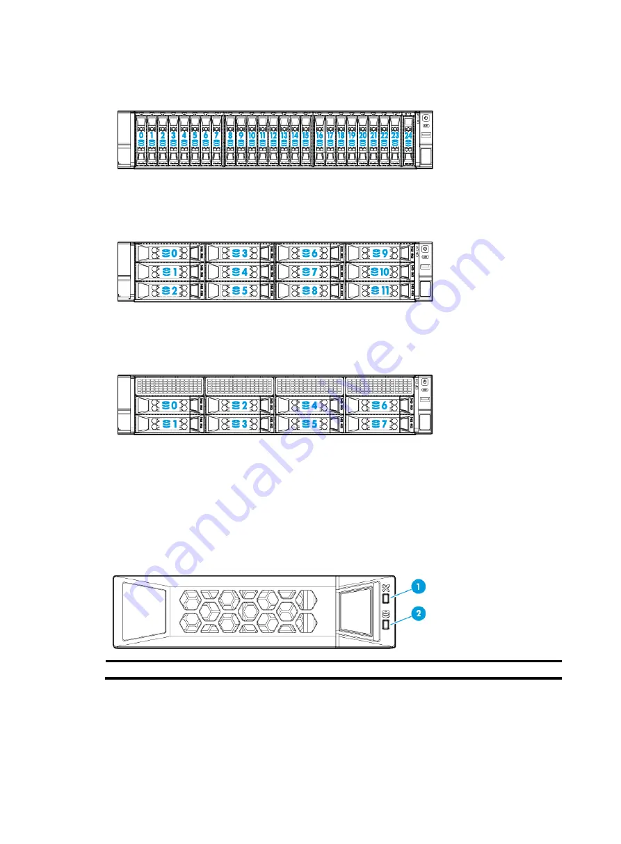
UIS-Cell 3020 G3 

Figure 198 Drive numbering 


UIS-Cell 3030 G3 

Figure 199 Drive numbering  


UIS-Cell 3040 G3 

Figure 200 Drive numbering 


Drive LEDs 

The server supports SAS and SATA drives, which are hot swappable. You can use the LEDs on a 
drive to identify its status after it is connected to a storage controller. 

Figure 201

 shows the location of the LEDs on a drive. 

Table 25

 describes the status of the LEDs. 

Figure 201 Drive LEDs 


(1) Fault/UID LED 

(2) Present/Active LED 


Содержание UIS-Cell 3000 G3

Страница 1: ...H3C UIS Cell 3000 G3 Hyper Converged Infrastructure User Guide New H3C Technologies Co Ltd http www h3c com Document version 5W101 20190131...

Страница 2: ...espective owners Notice The information in this document is subject to change without notice All contents in this document including statements information and recommendations are believed to be accur...

Страница 3: ...s button names field names and menu items are in Boldface For example the New User window opens click OK Multi level menus are separated by angle brackets For example File Create Folder Symbols Conven...

Страница 4: ...s 9 Connecting external cables 9 Cabling guidelines 9 Connecting a mouse keyboard and monitor 9 Connecting an Ethernet cable 11 Connecting a USB device 12 Connecting the power cord 13 Securing cables...

Страница 5: ...le 63 Installing GPU modules 65 Guidelines 65 Installing a GPU module without a power cord 66 Installing a GPU module with a power cord 68 Installing Ethernet adapters 69 Guidelines 69 Installing an m...

Страница 6: ...is ear 120 Replacing the left chassis ear 123 Connecting internal cables 125 Connecting drive cables 125 UIS Cell 3010 G3 server 125 UIS Cell 3020 G3 server 127 UIS Cell 3030 G3 server 129 UIS Cell 30...

Страница 7: ...M slots 150 Appendix B Component specifications 151 About component model names 151 Optional components for the server 151 DIMMs 154 DIMM rank classification label 155 HDDs and SSDs 155 Drive configur...

Страница 8: ...any circumstances The surface or component might be hot and present burn hazards WARNING To avoid being burnt allow hot surfaces or components to cool before touching them The server or component is...

Страница 9: ...power cords that came with the server Do not use the power cords that came with the server for any other devices Power off the server when installing or removing any components that are not hot swapp...

Страница 10: ...s including wearing antistatic clothing static dissipative shoes and antistatic gloves Use conductive field service tools Use a portable field service kit with a folding static dissipating work mat Co...

Страница 11: ...he battery to a temperature higher than 60 C 140 F Do not disassemble crush puncture short external contacts or dispose of the battery in fire or water Dispose of the battery at a designated facility...

Страница 12: ...mum clearance of 1219 mm 47 99 in is reserved between racks Figure 1 Airflow through the server 1 to 4 Directions of the airflow into the chassis and power supplies 5 to 7 Directions of the airflow ou...

Страница 13: ...ucial to lightning protection anti interference and ESD prevention The server can be grounded through the grounding wire of the power supply system and no external grounding cable is required Installa...

Страница 14: ...r ESD prevention when you operate the server Antistatic gloves For ESD prevention when you operate the server Antistatic clothing For ESD prevention when you operate the server Ladder For high place o...

Страница 15: ...For information about installing the rails see the document shipped with the rails Rack mounting the server 1 Slide the server into the rack For more information about how to slide the server into the...

Страница 16: ...ipation make sure no cables block the inlet or outlet air vents of the server To easily identify ports and connect disconnect cables make sure the cables do not cross Label the cables for easy identif...

Страница 17: ...n the plug Figure 4 Connecting a VGA cable 2 Connect the other plug of the VGA cable to the VGA connector on the monitor and fasten the screws on the plug 3 Connect the mouse and keyboard For a USB mo...

Страница 18: ...ork port on the server For the position of the HDM network port see Rear panel view 2 Verify the connectivity of the cable by using a link tester If you are replacing the Ethernet cable make sure the...

Страница 19: ...n the front panel if an installed chassis ear contains a VGA connector a USB 2 0 connector and a USB 3 0 connector Two USB 3 0 connectors on the rear panel Two internal USB 2 0 connector for connectin...

Страница 20: ...stall the driver for the USB device If the server still fails to identify the USB device after the driver is installed replace the USB device Connecting the power cord Guidelines WARNING To avoid dama...

Страница 21: ...of the power cord a Optional If the cable clamp is positioned too near the power cord and blocks the power cord plug connection press down the tab on the cable mount and slide the clamp backward Figu...

Страница 22: ...ard Securing cables Securing cables to cable management brackets For information about how to secure cables to cable management brackets see the installation guide shipped with the brackets Securing c...

Страница 23: ...around the slide rail and loop the end of the cable strap through the buckle 3 Dress the cable strap to ensure that the extra length and buckle part of the strap are facing outside of the slide rail F...

Страница 24: ...17 Figure 13 Extending the server from the rack 4 Place the server on a clean stable surface...

Страница 25: ...s standby mode and supplies power to the system The system power LED changes from steady amber to flashing green and then to steady green For information about the position of the system power LED see...

Страница 26: ...amber This method forces the server to enter standby mode without properly exiting applications and the operating system If an application stops responding you can use this method to force a shutdown...

Страница 27: ...anel is steady green which indicates that the system is operating correctly For more information about the health LED status see LEDs and buttons Updating firmware IMPORTANT Verify the hardware and so...

Страница 28: ...S Manager Make sure the browser and resolution setting of the configuration terminal meet the requirements in Table 5 Table 5 Browser and resolution requirements Browsers Resolution Google Chrome 45 0...

Страница 29: ...network the Configuration screen displays the UIS Manager IP address obtained from the DHCP server If no DHCP server exists in the management network the network parameter fields on the Configuration...

Страница 30: ...mpute virtualization deployment Deploys only Cloud Virtualization Kernel CVK and provides storage services through an IP SAN or FC SAN A minimum of one UIS host is required HCI deployment Deploys both...

Страница 31: ...24 Figure 17 Selecting the system language 3 On the UIS Setup Wizard page click Virtualization Figure 18 Selecting a scenario 4 Configure network parameters as needed and then click Next...

Страница 32: ...ration tip NOTE If the start IP address is different from the management interface IP used for login the system refreshes the page and opens the Hosts page by using the start IP address At next login...

Страница 33: ...nagement IP address of the management node is the specified start IP address on the Network page and cannot be modified If you do not specify a management IP address for a storage or monitor node the...

Страница 34: ...stination IP address source port number and destination port number of packets Basic Load balances physical NICs based on the source MAC address and VLAN tag of packets Active Standby Load balances th...

Страница 35: ...based switching between VMs hosts and the external network Perform this task only when IP SAN storage is used To add a virtual switch 1 On the top navigation bar click Networks and then select vSwitc...

Страница 36: ...reate a virtual switch Figure 28 Configuring host information 6 Click the icon for each host to configure physical interface information On the window that opens select one physical interface or two p...

Страница 37: ...network shared IP SAN storage start from step 1 To configure network shared FC SAN storage start from step 4 To configure network shared storage 1 On the top navigation bar click Hosts and then selec...

Страница 38: ...k Storage on the top navigation bar and select Shared Storage from the navigation pane Figure 32 Configuring shared storage 5 Click Add 6 Configure the following parameters Type To access an IP SAN st...

Страница 39: ...field is required for an iSCSI shared directory NAA Specify the network addressing authority identifier for the LUN which is a unique identifier of the LUN on the storage server For an iSCSI shared di...

Страница 40: ...35 Confirming the shared storage adding operation 12 In the dialog box that opens click OK to format the shared file system Figure 36 Formatting the shared file system After shared storage configurati...

Страница 41: ...34 Figure 37 Selecting a scenario 3 Configure network parameters and then click Next Figure 38 Configuring network parameters 4 In the dialog box that opens click OK Figure 39 Configuration tip...

Страница 42: ...ke effect make sure the other hosts have active physical interfaces of the same names as those on this host and the interface speeds are as required If a host cannot meet the requirements you must con...

Страница 43: ...er is displayed only when multiple physical interfaces are configured for the management network Advanced Load balances physical NICs based on the Ethernet type IP protocol source IP address destinati...

Страница 44: ...on the Network page as shown in Figure 40 and then verify the host settings Figure 44 Verifying host settings 14 Click OK The system starts to configure the host Figure 45 Configuring the host 15 On...

Страница 45: ...ite cache partitions for all HDDs must be smaller than the SSD size specified for the write cache This field is required when the deployment mode is SSD Caches HDDs Read Cache HDD Specify the size of...

Страница 46: ...39 Figure 48 Deploying distributed storage...

Страница 47: ...an official edition The trial and official editions provide the same functions Obtaining host information files 1 Access the UIS Manager login page at http manage_node_management_IP 8080 or https mana...

Страница 48: ...Click Download The host information file package is downloaded to the local disk The name of the host information file package is UIS_hosts_info tar gz by default The package contains two files CAS_ho...

Страница 49: ...ense file select Cloud_H3C Automation System as the product category upload file CAS_host info and click Get activation key or file To obtain a distributed storage license file select Distributed Stor...

Страница 50: ...ot user password admin by default and select Register the Product by Using the License from the License Actions field Then click Next Figure 54 Specifying a license action 4 Click Browse to select the...

Страница 51: ...Manager 2 On the top navigation bar click System and then select Licensing from the navigation pane 3 Click Register License 4 Click Browse to upload a distributed storage license file lic file Figure...

Страница 52: ...security bezel as shown by callout 4 in Figure 57 Then pull out the key and keep it safe CAUTION To avoid damage to the lock hold down the key while you are turning the key Figure 57 Installing the s...

Страница 53: ...As a best practice install drives of the same model for a server Procedure 1 Remove the security bezel if any For more information see Replacing the security bezel 2 Press the latch on the drive blank...

Страница 54: ...e the drive LEDs to verify that the drive is operating correctly For more information see Drive LEDs Installing power supplies Guidelines The power supplies are hot swappable Make sure the installed p...

Страница 55: ...to verify that the power supply is operating correctly For more information about the power supply LED see LEDs in Rear panel Log in to HDM to verify that the power supply is operating correctly For...

Страница 56: ...2 Installing a UIS RC GPU FHHL 2U G3 F1 riser card and a PCIe module UIS RC FHHL 2U G3 F 3 Installing a UIS RC FHHL 2U G3 F riser card and a PCIe module NOTE A riser card bracket is required UIS RC 2...

Страница 57: ...he PCIe module blank in the target PCIe slot and then pull the blank out of the slot as shown in Figure 64 Figure 64 Removing the PCIe module blank b Insert the PCIe module into the slot along the gui...

Страница 58: ...rver For more information see Powering on the server Installing a UIS RC GPU FHHL 2U G3 F1 riser card and a PCIe module 1 Power off the server For more information see Powering off the server 2 Remove...

Страница 59: ...nk out of the slot as shown in Figure 68 Figure 68 Removing the PCIe module blank b Insert the PCIe module into the slot along the guide rails and use the screw to secure it into place as shown in Fig...

Страница 60: ...cting the power cord 11 Power on the server For more information see Powering on the server Installing a UIS RC FHHL 2U G3 F riser card and a PCIe module 1 Power off the server For more information se...

Страница 61: ...d then pull the blank out of the slot as shown in Figure 72 Figure 72 Removing the PCIe module blank b Insert the PCIe module into the slot along the guide rails and use the screw to secure it into pl...

Страница 62: ...ccess panel 10 Rack mount the server For more information see Rack mounting the server 11 Connect the power cord For more information see Connecting the power cord 12 Power on the server For more info...

Страница 63: ...rd a Remove the screw on the PCIe module blank in the target PCIe slot and then pull the blank out of the slot as shown in Figure 76 Figure 76 Removing the PCIe module blank b Insert the PCIe module i...

Страница 64: ...e riser card blank 10 Install the power supply air baffle For more information see Installing air baffles 11 Connect PCIe module cables if any 12 Install the access panel For more information see Inst...

Страница 65: ...stall the PCIe module on the riser card a Remove the screw on the PCIe module blank in the target PCIe slot and then pull the blank out of the slot as shown in Figure 81 Figure 81 Removing the PCIe mo...

Страница 66: ...a flash card and a supercapacitor When a system power failure occurs this supercapacitor can provide power for a minimum of 20 seconds During this interval the storage controller transfers data from D...

Страница 67: ...connectors 1 and 2 if any For more information see Replacing a riser card and a PCIe module 7 Align the pin holes in the Mezzanine storage controller with the guide pins on the system board Insert the...

Страница 68: ...internal threaded studs Figure 86 Installing the flash card b Install the supercapacitor holder in the server chassis as shown in Figure 87 Make sure its bottom flanges are seated in the grooves for...

Страница 69: ...age controller to the supercapacitor For more information see Connecting the flash card on the Mezzanine storage controller e Connect drive data cables to the Mezzanine storage controller For more inf...

Страница 70: ...2 Remove the server from the rack For more information see Removing the server from a rack 3 Remove the access panel For more information see Removing the access panel 4 Remove the air baffles as nee...

Страница 71: ...e standard storage controller to the server by using a riser card For more information see Installing riser cards and PCIe modules 8 Optional Install the supercapacitor of the power fail safeguard mod...

Страница 72: ...rver For more information see Rack mounting the server 14 Connect the power cord For more information see Connecting the power cord 15 Power on the server For more information see Powering on the serv...

Страница 73: ...1 2 and 3 This section uses the riser card on PCIe riser connector 1 as an example Procedure 1 Determine the installation position 2 Power off the server For more information see Powering off the ser...

Страница 74: ...95 Installing the riser card 8 Connect cables for the GPU module as needed 9 Install the access panel For more information see Installing the access panel 10 Rack mount the server For more information...

Страница 75: ...mation see Removing the access panel 5 Remove the PCIe riser card blank from PCIe riser connector 1 as shown in Figure 63 6 Remove the screw from the target PCIe slot and then pull the blank out of th...

Страница 76: ...dapters Guidelines You can install an mLOM Ethernet adapter only in the mLOM Ethernet adapter connector on the system board For more information about the connector location see System board component...

Страница 77: ...slot as shown in Figure 98 Figure 98 Removing the mLOM Ethernet adapter blank b Insert the mLOM Ethernet adapter into the slot along the guide rails and then fasten the captive screws to secure the Et...

Страница 78: ...more information see HDM online help Installing SATA M 2 SSDs Guidelines The SATA M 2 SSDs can only be installed in drive cage bay 1 on a UIS Cell 3010 G3 server For more information about the locati...

Страница 79: ...wn in Figure 100 Figure 100 Installing a SATA M 2 SSD b Connect the SATA M 2 SSD cable to the M 2 transfer module as shown in Figure 101 If you install only one SATA M 2 SSD use the cable marked with...

Страница 80: ...tical drive installation locations Optical drive Installation location USB 2 0 optical drive Connect the optical drive to a USB 2 0 or USB 3 0 connector on the server SATA optical drive IMPORTANT Only...

Страница 81: ...y callout 1 in Figure 103 The optical drive blank will pop out from the enablement option b Pull the blank out of the enablement option as shown by callout 2 in Figure 103 Figure 103 Removing the opti...

Страница 82: ...stall the removed security bezel For more information see Installing the security bezel 13 Install the removed fan cage For more information see Installing fans 14 Install the removed chassis air baff...

Страница 83: ...the other fans speed up and the Health LED on the front panel flashes amber at 1 Hz to indicate that a general warning was generated If two fans fail the Health LED on the front panel flashes red at 1...

Страница 84: ...ling DIMMs Guidelines WARNING The DIMMs are not hot swappable Each processor supports six DIMM channels Each DIMM channel has two DIMM slots You can install a maximum of 12 DIMMs for each processor Fo...

Страница 85: ...Install 8 DIMMs in slots A1 A2 A4 A5 B1 B2 B4 and B5 Install 9 DIMMs in slots A1 A2 A3 A4 A5 A6 B1 B2 and B3 Install 12 DIMMs in slots A1 A2 A4 A5 A7 A8 A10 A11 B1 B2 B7 and B8 or slots A1 to A6 and...

Страница 86: ...le For more information see Installing air baffles 7 Install the access panel For more information see Installing the access panel 8 Rack mount the server For more information see Installing the serve...

Страница 87: ...oid ESD damage put on an ESD wrist strap before performing this task and make sure the wrist strap is reliably grounded Procedure 1 Back up all server data 2 Power off the server For more information...

Страница 88: ...ning bracket onto the heatsink CAUTION When you remove the protective cover over the heatsink be careful not to touch the thermal grease on the heatsink a Lift the cover straight up until it is remove...

Страница 89: ...le Damage to pins will incur system board replacement Keep the pins on the processor socket clean Make sure the socket is free from dust and debris Hold the cover by the notches on its two edges and l...

Страница 90: ...Installing air baffles 13 Install the access panel For more information see Installing the access panel 14 Rack mount the server For more information see Installing the server 15 Connect the power cor...

Страница 91: ...release the latch as shown by callouts 2 and 3 in Figure 115 3 Pull the right edge of the security bezel out of the groove in the right chassis ear to remove the security bezel as shown by callout 4...

Страница 92: ...n about drive LEDs see Drive LEDs Replacing the access panel WARNING To avoid bodily injury from hot surfaces allow the server and its internal modules to cool before touching them CAUTION To avoid th...

Страница 93: ...e a T15 Torx screwdriver to unlock the locking lever 2 Press the latch on the locking lever pull the lever upward and then release the latch as shown in Figure 118 Figure 118 Opening the locking lever...

Страница 94: ...space is available for replacement you can replace a power supply without powering off or removing the server from the rack Procedure 1 Power off the server For more information see Powering off the...

Страница 95: ...n slot 2 6 Mount the server in the rack For more information see Installing the server 7 Connect the power cord For more information see Connecting the power cord 8 Power on the server For more inform...

Страница 96: ...e you also need to remove the GPU P100 GPU module For more information about removing a riser card and a GPU module see Replacing a riser card and a PCIe module and Replacing a GPU module 5 Remove air...

Страница 97: ...Install air baffles To install the chassis air baffle place the air baffle on top of the chassis with the standouts at both ends of the air baffle aligned with the notches on the chassis edges as sho...

Страница 98: ...power cord For more information see Connecting the power cord 7 Power on the server For more information see Powering on the server Replacing a riser card and a PCIe module WARNING To avoid bodily in...

Страница 99: ...access panel 9 Mount the server in the rack For more information see Installing the server 10 Connect the power cord For more information see Connecting the power cord 11 Power on the server For more...

Страница 100: ...ent model back up data in drives and then clear RAID information before the replacement Replacing the Mezzanine storage controller Procedure 1 Power off the server For more information see Powering of...

Страница 101: ...15 Rack mount the server For more information see Rack mounting the server 16 Connect the power cord For more information see Connecting the power cord 17 Power on the server For more information see...

Страница 102: ...nformation see Powering on the server Verifying the replacement Log in to HDM to verify that the standard storage controller is in a correct state For more information see HDM online help Replacing th...

Страница 103: ...supercapacitor 9 Pull the clip on the supercapacitor holder take the supercapacitor out of the holder and then release the clip as shown in Figure 130 Figure 130 Removing the supercapacitor 10 Lift th...

Страница 104: ...erver Verifying the replacement Log in to HDM to verify that the flash card and the supercapacitor are in a correct state For more information see HDM online help Replacing the power fail safeguard mo...

Страница 105: ...more information see Installing the access panel 14 Rack mount the server For more information see Rack mounting the server 15 Connect the power cord For more information see Connecting the power cord...

Страница 106: ...e GPU module if any as shown by callouts 3 and 4 in Figure 134 This example uses UIS GPU M60 1 GPU module in PCIe slot 1 to show the procedure Not all GPU modules have power cords Figure 134 Removing...

Страница 107: ...nd then pull the Ethernet adapter out of the slot as shown in Figure 135 Figure 135 Removing an mLOM Ethernet adapter 4 Install a new mLOM Ethernet adapter For more information see Installing an mLOM...

Страница 108: ...rmation see HDM online help Replacing a M 2 transfer module and a SATA M 2 SSD WARNING To avoid bodily injury from hot surfaces allow the server and its internal modules to cool before touching them T...

Страница 109: ...ng a fan WARNING To avoid bodily injury from hot surfaces allow the server and its internal modules to cool before touching them CAUTION To avoid thermal damage to the server do not operate the server...

Страница 110: ...see HDM online help Replacing the fan cage WARNING To avoid bodily injury from hot surfaces allow the server and its internal modules to cool before touching them To replace the fan cage 1 Power off...

Страница 111: ...see Powering on the server Replacing a DIMM WARNING To avoid bodily injury from hot surfaces allow the server and its internal modules to cool before touching them Procedure 1 Power off the server Fo...

Страница 112: ...Replacing a processor WARNING To avoid bodily injury from hot surfaces allow the server and its internal modules to cool before touching them Guidelines To avoid damage to a processor or the system bo...

Страница 113: ...sink slowly to remove it as shown by callout 5 in Figure 140 Figure 140 Removing a processor heatsink 6 Remove the processor retaining bracket from the heatsink a Insert a flat head tool such as a fla...

Страница 114: ...ocessor as shown in Figure 142 Figure 142 Separating the processor from the retaining bracket Installing a processor 1 Install the processor onto the retaining bracket For more information see Install...

Страница 115: ...processors 5 Past bar code label supplied with the processor over the original processor label on the heatsink IMPORTANT This step is required for you to obtain H3C s processor servicing 6 Optional R...

Страница 116: ...For more information see Powering on the server Replacing the system battery WARNING To avoid bodily injury from hot surfaces allow the server and its internal modules to cool before touching them Th...

Страница 117: ...ess the system battery to seat it in the holder as shown by callout 2 in Figure 147 Figure 147 Installing the system battery 3 Optional Install the removed PCIe modules For more information see Instal...

Страница 118: ...fan cage For more information see Replacing the fan cage 7 Disconnect all cables connected to the system board 8 Remove the PCIe riser cards and PCIe modules if any For more information see Replacing...

Страница 119: ...ward the server rear until the connectors for example USB connectors and the Ethernet port on it are securely seated as shown by callout 1 in Figure 149 NOTE The connectors are securely seated if you...

Страница 120: ...rver 14 Connect the power cord For more information see Connecting the power cord 15 Power on the server For more information see Powering on the server Verifying the replacement Log in to HDM to veri...

Страница 121: ...he expander module against the drive backplane Fasten the captive screws to secure the expander module into place as shown in Figure 151 Figure 151 Installing a 12LFF drive expander module For the 25S...

Страница 122: ...the drive expander module is in a correct state and no alert is generated For more information see HDM online help Replacing the drive backplane WARNING To avoid bodily injury from hot surfaces allow...

Страница 123: ...e is the same for the servers This procedure removes the drive backplane from the UIS Cell 3020 G3 server CAUTION Do not use excessive force when lifting the drive backplane out of the chassis Using e...

Страница 124: ...er For more information see Rack mounting the server 10 Connect the power cord For more information see Connecting the power cord 11 Power on the server For more information see Powering on the server...

Страница 125: ...stalling air baffles 14 Install the access panel For more information see Installing the access panel 15 Rack mount the server For more information see Rack mounting the server 16 Connect the power co...

Страница 126: ...he left chassis ear This figure uses the chassis open alarm module attached to the left chassis ear as an example 5 Remove the left chassis ear if the chassis open alarm module is attached to the left...

Страница 127: ...ore information see Powering on the server Replacing chassis ears WARNING To avoid bodily injury from hot surfaces allow the server and its internal modules to cool before touching them Replacing the...

Страница 128: ...oward the rear of the chassis and then remove it from the chassis as shown by callouts 1 and 2 in Figure 159 c Pull the I O component cable out of the slot as shown by callout 3 in Figure 159 Figure 1...

Страница 129: ...the front I O component cable assembly into the cable cutout as shown by callout 1 in Figure 162 b Attach the cable protection plate to the chassis front of the server with its keyed slots over the pe...

Страница 130: ...ng the fan cage 4 Install the chassis air baffle For more information see Installing air baffles 5 Install the access panel For more information see Installing the access panel 6 Rack mount the server...

Страница 131: ...procedure is the same for the left and right chassis ears For more information see Removing the right chassis ear Installing the left chassis ear 1 Install the left chassis ear The installation proce...

Страница 132: ...SATA drive backplane to a storage controller depending on the type of the storage controller Table 9 8SFF SAS SATA drive cabling methods Storage controller Cabling method Embedded RSTe RAID controlle...

Страница 133: ...standard storage controller 1 AUX signal cable 2 Power cord 3 SAS SATA data cable NOTE The cabling method is the same for standard storage controllers in PCIe slots 2 and 6 of riser cards This figure...

Страница 134: ...2 for drive cage bay 3 UIS Cell 3020 G3 server 25SFF SAS SATA drive cabling Use Table 10 to select the method for connecting the 25SFF SAS SATA drive backplane to a storage controller depending on the...

Страница 135: ...d 1 3 Power cord 2 4 SAS SATA data cable Figure 169 25SFF SAS SATA drive backplane connected to a standard storage controller 1 AUX signal cable 2 Power cord 1 3 Power cord 2 4 SAS SATA data cable IMP...

Страница 136: ...ds Storage controller Cabling method Mezzanine storage controller See Figure 170 Standard storage controller See Figure 171 Figure 170 12LFF SAS SATA drive backplane connected to the Mezzanine storage...

Страница 137: ...FF drive backplane to a storage controller depending on the type of the storage controller Table 12 8LFF drive cabling methods Storage controller Cabling method Embedded RSTe RAID controller See Figur...

Страница 138: ...3 SAS SATA data cable NOTE The cabling method is the same for standard storage controllers in PCIe slots 2 and 6 of riser cards This figure uses slot 6 as an example Connecting the flash card and sup...

Страница 139: ...rage controller Connecting the flash card on a standard storage controller The cabling method is the same for standard storage controllers in PCIe slots 1 2 6 and 8 Figure 176 uses slot 1 to show the...

Страница 140: ...trollers in any PCIe slots Figure 178 uses slot 1 to show the cabling method Figure 178 Connecting the NCSI transit cable for a PCIe Ethernet adapter Connecting the SATA M 2 SSD cable The SATA M 2 SSD...

Страница 141: ...SD cable one SATA M 2 SSD Figure 180 Connecting the SATA M 2 SSD cable two SATA M 2 SSDs Connecting the SATA optical drive cable Connect the SATA optical drive cable as shown in Figure 181 Figure 181...

Страница 142: ...d as shown in Figure 182 Figure 182 Connecting the front I O component cable assembly 1 Front I O LED cable 2 USB 3 0 connector cable Connecting the cable for the front VGA and USB 2 0 connectors on t...

Страница 143: ...bleshooting Maintenance tools The following are major tools for server maintenance Hygrothermograph Monitor the operating environment of the server HDM and FIST Monitor the operating status of the ser...

Страница 144: ...equirements described in Appendix A Server specifications Examining cable connections Verify that the cables and power cords are correctly connected Guidelines Do not use excessive force when connecti...

Страница 145: ...model and name Snapshots of error messages and descriptions Hardware change history including installation replacement insertion and removal of hardware Third party software installed on the server O...

Страница 146: ...HCI core and UIS Manager The UIS Cell HCI system integrates the CAS Cloud Virtualization Kernel CVK and UIS Manager H3C CAS CVK isolates guest OSs and applications on VMs from the underlying hardware...

Страница 147: ...B connectors 5 USB 3 0 connectors one at the server front two at the server rear and two on the system board 1 USB 2 0 connector provided by the left chassis ear with a USB 2 0 connector 9 SATA connec...

Страница 148: ...158 F Humidity Operating humidity 8 RH to 90 RH noncondensing Storage humidity 5 RH to 90 RH noncondensing Altitude Operating altitude 60 m to 3000 m 196 85 ft to 9842 52 ft The allowed maximum temper...

Страница 149: ...of a server on which multiple components are installed such as processor memory and fan It is integrated with basic server components including the BIOS chip HDM chip and PCIe riser connectors 7 Stora...

Страница 150: ...ing data and data exchanged with external storage 23 Supercapacitor Supplies power to the flash card of the power fail safeguard module which enables the storage controller to back up data to the flas...

Страница 151: ...VGA connector optional 2 USB 2 0 connector optional 3 USB 3 0 connector 4 SAS SATA drives 5 SAS SATA drives Figure 189 UIS Cell 3040 G3 front panel 1 VGA connector optional 2 USB 2 0 connector optiona...

Страница 152: ...alarm has occurred If a system alarm is present log in to HDM to obtain more information about the system running status mLOM Ethernet adapter Ethernet port LED Steady green A link is present on the...

Страница 153: ...nnection is needed as shown in Table 16 Table 16 Optional ports on the front panel Port Type Description USB connector USB 3 0 2 0 Connects the following devices USB flash drive USB keyboard or mouse...

Страница 154: ...present on the port Off No link is present on the port Activity LED of the Ethernet port Flashing green 1 Hz The port is receiving or sending data Off The port is not receiving or sending data UID LE...

Страница 155: ...Off No power supplies have power input which can be caused by an incorrect power cord connection or power source shutdown Ports Table 18 Ports on the rear panel Port Type Description HDM dedicated ne...

Страница 156: ...or 8 Ethernet adapter NCSI function connector 9 Mini SAS port x8 SATA ports 10 Front I O connector 11 Optical SATA port 12 Front drive backplane power connector 1 13 Dual internal USB 3 0 connector 14...

Страница 157: ...e BIOS at server startup System maintenance switch 3 Pins 1 2 jumped default Normal server startup Pins 2 3 jumped Restores the default BIOS settings For this purpose jump pins 2 and 3 for over 30 sec...

Страница 158: ...F 5115 2 4 GHz 10 cores 13 75 MB 85 W processor UIS CPU 5118 2U F 5118 2 3 GHz 12 cores 16 5 MB 105 W processor UIS CPU 5120 2U F 5120 2 2 GHz 14 cores 19 25 MB 105 W processor UIS CPU 5120T 2U F 5120...

Страница 159: ...UIS HDD 2T SATA 6G 7 2K SFF F2 2TB 6G SATA 7 2K 2 5 inch EV 512e HDD SSD drives UIS SSD 3 84T SATA 6G SFF i F 3 84TB 6G SATA 2 5 inch EV S4500 SSD i UIS SSD 1 92T SATA 6G SFF i F 1 92TB 6G SATA 2 5 in...

Страница 160: ...F i F 240GB 6G SATA 3 5 inch EV S4500 SSD i UIS SSD 480G SATA 6G LFF i F1 480GB 6G SATA 3 5 inch EV S4500 SSD UIS SSD 800G SATA 6G LFF F2 800GB 6G SATA 3 5 inch EM SSD UIS SSD 240G SATA 6G EV SCL i F...

Страница 161: ...8Gb 2P 2 port 8Gb fiber channel HBA with two SFP transceiver modules UIS FC HBA QLE2692 16Gb 2P 2 port 16Gb fiber channel HBA with two SFP transceiver modules GPU module UIS GPU M60 1 UIS GPU M60 2 F...

Страница 162: ...ion Callout Description Remarks 1 Capacity N A 2 Number of ranks N A 3 Data width x4 4 bits x8 8 bits 4 DIMM generation Only DDR4 is supported 5 Data rate 2133P 2133 MHz 2400T 2400 MHz 2666V 2666 MHz...

Страница 163: ...ring UIS Cell 3010 G3 Table 24 Drive population and drive numbering schemes Drive configuration Drive cage bay 1 Drive cage bay 2 Drive cage bay 3 Drive numbering 8SFF Unused Used Unused See Figure 19...

Страница 164: ...ng Drive LEDs The server supports SAS and SATA drives which are hot swappable You can use the LEDs on a drive to identify its status after it is connected to a storage controller Figure 201 shows the...

Страница 165: ...ller PCIe modules Typically the PCIe modules are available in the following standard form factors LP Low profile FHHL Full height and half length FHFL Full height and full length HHHL Half height and...

Страница 166: ...afeguard module UN Flash PMC G2 The power fail safeguard module is optional UIS RAID LSI 9361 8i 1G Item Specifications Type Mezzanine storage controller Number of internal ports 8 internal SAS ports...

Страница 167: ...e You must connect a separate power cord to the PCIe module if it requires more than 75 W power Riser cards for riser connector 1 or 2 If a riser card can be installed on riser connector 1 or 2 the sl...

Страница 168: ...ector 1 Connector 2 PCIe slots Slot 2 5 PCIe3 0 16 16 8 4 2 1 Slot 3 6 PCIe3 0 8 8 4 2 1 NOTE The numbers in parentheses represent link widths Form factors of PCIe modules FHHL only slot 2 5 supports...

Страница 169: ...Form factors of PCIe modules FHHL Maximum power supplied per PCIe slot 75 W Figure 204 PCIe slots on the UIS RC FHHL 2U G3 F riser card 1 PCIe slot 7 2 PCIe slot 8 UIS RC 2 LP 2U G3 F Item Specificati...

Страница 170: ...PCIe3 0 8 8 4 2 1 NOTE The numbers in parentheses represent link widths Form factors of PCIe modules FHHL only slot 7 supports single wide and double wide GPU modules Maximum power supplied per PCIe s...

Страница 171: ...164 Figure 207 Fan layout...

Отзывы: