


Chapter 4 Machine Debugging
175
Inst
allation
and
Ⅳ
connection
C. The machine’s reference point is at the machine’s middle point, which occurs when an
absolute encoder is allocated. The machine coordinate system’s least value in the area is -100
,
the compensation number of -50 point is No. 0, the position relationship between the reference
point and No. 0 compensation point is No. 5, which is shown in Fig. 4-7-3:
Compensation
number
Machine
coordinate value
0
1
2
3
4
5
6
7
8
9
10
-50
-40
-30
-20
-10
0
10
20
30
40
50
(
Machine zero
)
The reference point is the middle point of the stroke
Fig. 4-7-3
Note: Relevant parameters with each pitch error are set according to the actual condition when the
pitch error is checked. If the setting is mistaken, the machine precision is reduced.
z
Corresponding relationship between the pitch error compensation amount and
reference point’s compensation sequence number
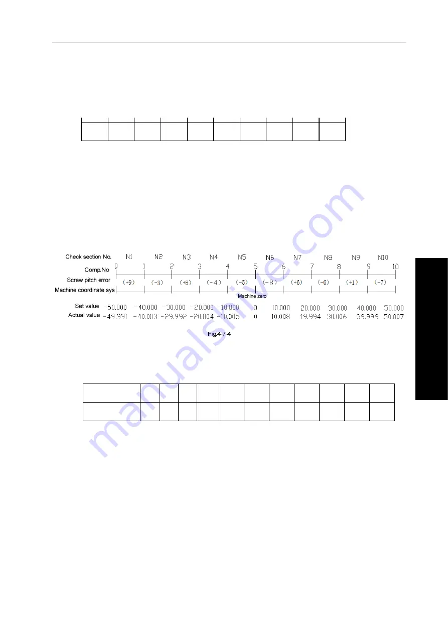
Corresponding relationship between the pitch error compensation amount and the
compensation number is shown in Fig. 4-7-4:
Corresponding relationship between the pitch error compensation amount and compensation
number is shown in Table 4-7-1:
Table 4-7-1
Compensation
number
0
1
2
3 4 5 6 7 8 9 10
Compensation
amount
0
+9
-3
+8
-4 -5 -8 +6 -6 +1 -7
Distance between the least value and the max value of the machine worktable’s moving stroke
is divided into N blocks, the pitch error of each block’s interval is fixed, which is not influenced by
the worktable’s moving direction. The error value in N1 area is input into the corresponding
sequence number “1”, the system can correctly call N1 area’ pitch error compensation amount
as Fig. 4-7-4, the error value in N6 area is input into the corresponding compensation sequence
number “6”, so, the system can correctly call N6 area’s pitch error compensation amount. So, the
relationship is each area’s pitch error value corresponding to the relative area’ end point of the
positive moving.
z
Pitch error compensation set’s example
The linear axis pitch error compensation example, the linear axis takes X as example, and other
axes’ setting methods are the same.
A. Positive zero return, the error compensation is checked by taking the machine zero as the
reference point.
Содержание 980TC3 Series
Страница 13: ...1 Programming Ⅰ Programming Ⅰ ...
Страница 14: ...GSK980TC3 Series Bus Turning CNC system PLC Installation and Connection User Manual 2 一 Programming ...
Страница 24: ...GSK980TC3 Series Bus Turning CNC system PLC Installation and Connection User Manual 12 一 Programming ...
Страница 32: ...GSK980TC3 Series Bus Turning CNC system PLC Installation and Connection User Manual 20 一 Programming ...
Страница 71: ...59 Operation Ⅱ Ⅱ Operation ...
Страница 72: ...GSK980TC3 Series Bus Turning CNC system PLC Installation and Connection User Manual 60 Ⅱ Operation ...
Страница 86: ...GSK980TC3 Series Bus Turning CNC system PLC Installation and Connection User Manual 74 Ⅱ Operation ...
Страница 96: ...GSK980TC3 Series Bus Turning CNC system PLC Installation and Connection User Manual 84 Ⅱ Operation ...
Страница 97: ...85 III Ⅲ Function III Function ...
Страница 98: ...GSK980TC3 Series Bus Turning CNC system PLC Installation and Connection User Manual 86 Ⅲ Function ...
Страница 114: ...GSK980TC3 Series Bus Turning CNC system PLC Installation and Connection User Manual 102 Ⅲ Function ...
Страница 136: ...GSK980TC3 Series Bus Turning CNC system PLC Installation and Connection User Manual 124 Ⅲ Function ...
Страница 138: ...GSK980TC3 Series Bus Turning CNC system PLC Installation and Connection User Manual 126 Ⅲ Function ...
Страница 140: ...GSK980TC3 Series Bus Turning CNC system PLC Installation and Connection User Manual 128 Ⅲ Function ...
Страница 148: ...GSK980TC3 Series Bus Turning CNC system PLC Installation and Connection User Manual 136 Ⅲ Function ...
Страница 149: ...137 Installation and Connection Ⅳ Ⅳ Installation and Connection ...
Страница 150: ...GSK980TC3 Series Bus Turning CNC system PLC Installation and Connection User Manual 138 Installation and Connection Ⅳ ...
Страница 156: ...GSK980TC3 Series Bus Turning CNC system PLC Installation and Connection User Manual 144 Installation and Connection Ⅳ ...
Страница 208: ...GSK980TC3 Series Bus Turning CNC system PLC Installation and Connection User Manual 196 Appendix Appendix ...
Страница 209: ...197 附 录 Appendix ...
Страница 218: ...GSK980TC3 Series Bus Turning CNC system PLC Installation and Connection User Manual 206 Appendix ...
Страница 226: ...GSK980TC3 Series Bus Turning CNC system PLC Installation and Connection User Manual 214 Appendix ...


