


GSK980TC3 Series Bus Turning CNC system PLC, Installation and Connection User Manual
170
Inst
allation
and
Connection
Ⅳ
The fractional frequency and frequency multiplication( the electrical gear) of the position code
pulse should be set.
In the Position control mode, the various pulse sources can be matched conveniently by setting
the parameters; therefore, the ideal controlled resolution ratio (angle/pulse) required by the customer
can be reached.
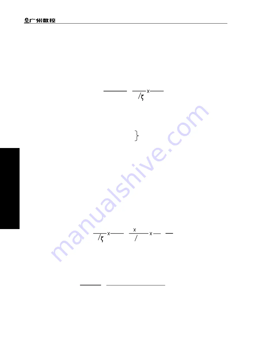
Formula:
G
L
Z
M
Z
D
=
Numerator
Denominator
=
4C
G: Electrical gear ratio;
L: Screw lead;
ζ
:The minimum output code unit of the system(mm/pulse);
C: The linear/revolution of the photoelectric encoder.
Z
M:
The number of gear teeth at the end of the screw.
Z
D:
The number of gear teeth at the end of the motor.
System side:
Frequency of the numerator: NO.160, NO.161, NO.162, NO.163, NO.164 of the system parameters
(the code frequency multiplication coefficient).
Frequency of the denominator: NO.165, NO.166, NO.167, NO.168, NO.169 of the system
parameters ( the code fractional frequency coefficient).
Digit servo side:
Frequency of the numerator: Parameter PA12 (The code frequency multiplication coefficient).
Frequency of the denominator: Parameter PA13 (The code fractional frequency coefficient).
【
Example 1
】
If the screw lead is 8mm, the minimum output code unit of the system is 0.001mm, and
the motor coder linear number is 2500, so:
G
L
Z
M
Z
D
=
=
4C
8 0.001
1
1
=
4 2500
5
4
Then, the data parameters NO. 160
(
CMRX
)
=5
,
NO.165
(
CMDX
)
=4;
The parameter setting of the system gear ratio is same as that of the digit servo gear ratio. If it is
equipped with the digit servo with the electrical gear ratio function, the electrical gear ratio of the
system is set as 1:1, and the calculated electrical gear ratio is set into the digit servo.
【
Example 2
】
The formular of the gear ratio of the rotation axis:
=
G
N
×
C
×
4
P
=
1
×
2500×4
360×1000×reduction ratio
(
driving/passive tooth
)
Note: the motor’s optical encoder lines C
=
2500.
4.5 Backlash Compensation
The dial gauge, the micrometer gauge or the laser can be used to measure; the backlash
compensation should be compensated to improve the machining precision. Therefore, measuring the
With the change gear
Содержание 980TC3 Series
Страница 13: ...1 Programming Ⅰ Programming Ⅰ ...
Страница 14: ...GSK980TC3 Series Bus Turning CNC system PLC Installation and Connection User Manual 2 一 Programming ...
Страница 24: ...GSK980TC3 Series Bus Turning CNC system PLC Installation and Connection User Manual 12 一 Programming ...
Страница 32: ...GSK980TC3 Series Bus Turning CNC system PLC Installation and Connection User Manual 20 一 Programming ...
Страница 71: ...59 Operation Ⅱ Ⅱ Operation ...
Страница 72: ...GSK980TC3 Series Bus Turning CNC system PLC Installation and Connection User Manual 60 Ⅱ Operation ...
Страница 86: ...GSK980TC3 Series Bus Turning CNC system PLC Installation and Connection User Manual 74 Ⅱ Operation ...
Страница 96: ...GSK980TC3 Series Bus Turning CNC system PLC Installation and Connection User Manual 84 Ⅱ Operation ...
Страница 97: ...85 III Ⅲ Function III Function ...
Страница 98: ...GSK980TC3 Series Bus Turning CNC system PLC Installation and Connection User Manual 86 Ⅲ Function ...
Страница 114: ...GSK980TC3 Series Bus Turning CNC system PLC Installation and Connection User Manual 102 Ⅲ Function ...
Страница 136: ...GSK980TC3 Series Bus Turning CNC system PLC Installation and Connection User Manual 124 Ⅲ Function ...
Страница 138: ...GSK980TC3 Series Bus Turning CNC system PLC Installation and Connection User Manual 126 Ⅲ Function ...
Страница 140: ...GSK980TC3 Series Bus Turning CNC system PLC Installation and Connection User Manual 128 Ⅲ Function ...
Страница 148: ...GSK980TC3 Series Bus Turning CNC system PLC Installation and Connection User Manual 136 Ⅲ Function ...
Страница 149: ...137 Installation and Connection Ⅳ Ⅳ Installation and Connection ...
Страница 150: ...GSK980TC3 Series Bus Turning CNC system PLC Installation and Connection User Manual 138 Installation and Connection Ⅳ ...
Страница 156: ...GSK980TC3 Series Bus Turning CNC system PLC Installation and Connection User Manual 144 Installation and Connection Ⅳ ...
Страница 208: ...GSK980TC3 Series Bus Turning CNC system PLC Installation and Connection User Manual 196 Appendix Appendix ...
Страница 209: ...197 附 录 Appendix ...
Страница 218: ...GSK980TC3 Series Bus Turning CNC system PLC Installation and Connection User Manual 206 Appendix ...
Страница 226: ...GSK980TC3 Series Bus Turning CNC system PLC Installation and Connection User Manual 214 Appendix ...


