


GSK980TC3 Series Bus Turning CNC system PLC, Installation and Connection User Manual
168
Inst
allation
and
Connection
Ⅳ
4.3 Emergency Stop and Limit
The system is with the software limit function. For safety, the hardware limit measure should be
adopted meanwhile, and the limit switches of each axis in positive and negative directions should be
installed.
About GSK980TC3 integration system, the user can monitor and check the state of the
emergency stop input signal through checking NO
:
009#4
(
*
ESP
)
on
【
X signal
】
software interface
of the <diagnosis> interface. After pressing the emergency stop button, all the air switches of the
system must be OFF.
In JOG or MPG mode, each coordinate axis is moved slowly to testify the validity of each axis
overrun limit switch, the overrun release button and the correctness of alarm display. The system
alarms when the overrun occurs or the emergency stop button is pressed; while press the overrun
release button and the axis moves oppositely, the system can release the alarm.
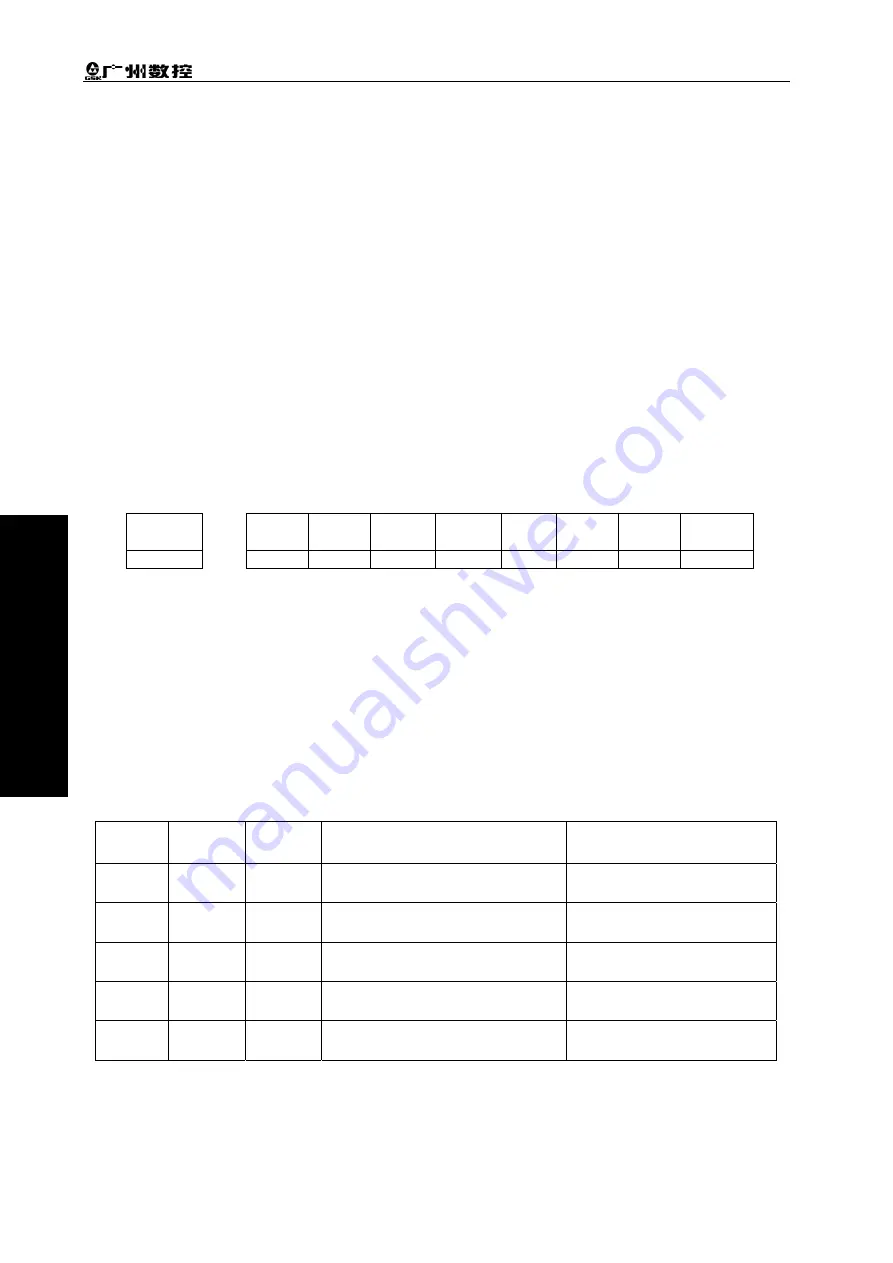
z
The emergency stop signal
GSK980TC3 parameter diagnosis (The input state on the system side)
Sate
address
X9.4
Pin NO.
XS40.19
Note: the system prompts:
0251
:
emergency stop alarm
,
980TC3 system checks X9.4.
It’s required to correctly display the alarm “some axis (the 1
st
axis or the 2
nd
or the 3
rd
axis) in
some direction (positive or negative) when the servo axis overruns. And it guarantees that after the
overrun is released, the axis can’t move in the overtravel direction when some axis overruns and the
alarm occurs. Therefore, GSK980TC3 system provides two connection methods of overrun limit
switches to satisfy the customers’ requirements.
A.
The situations of two limit switches:
(One limit switch of some axis in the positive direction, the other is in the negative)
1. Please strictly connect as the following list:
Table 4-3-1
Address
Signal
interface
Interface
pin
Definition Contact
X0.0
GL200
(
X0
)
0
Limit signal of the 1
st
axis stroke
Normally closed contact
X0.2
GL200
(
X0
)
2
Limit signal of the 3
rd
axis stroke
Normally closed contact
X4.0
GL200
(
X4
)
0
Limit signal of the 2
nd
axis stroke
Normally closed contact
X4.2
GL200
(
X4
)
2
Limit signal of the 4
th
axis stroke
Normally closed contact
X4.4
GL200
(
X4
)
4
Limit signal of the 5
th
axis stroke
Normally closed contact
2. Rewriting the following parameters:
Содержание 980TC3 Series
Страница 13: ...1 Programming Ⅰ Programming Ⅰ ...
Страница 14: ...GSK980TC3 Series Bus Turning CNC system PLC Installation and Connection User Manual 2 一 Programming ...
Страница 24: ...GSK980TC3 Series Bus Turning CNC system PLC Installation and Connection User Manual 12 一 Programming ...
Страница 32: ...GSK980TC3 Series Bus Turning CNC system PLC Installation and Connection User Manual 20 一 Programming ...
Страница 71: ...59 Operation Ⅱ Ⅱ Operation ...
Страница 72: ...GSK980TC3 Series Bus Turning CNC system PLC Installation and Connection User Manual 60 Ⅱ Operation ...
Страница 86: ...GSK980TC3 Series Bus Turning CNC system PLC Installation and Connection User Manual 74 Ⅱ Operation ...
Страница 96: ...GSK980TC3 Series Bus Turning CNC system PLC Installation and Connection User Manual 84 Ⅱ Operation ...
Страница 97: ...85 III Ⅲ Function III Function ...
Страница 98: ...GSK980TC3 Series Bus Turning CNC system PLC Installation and Connection User Manual 86 Ⅲ Function ...
Страница 114: ...GSK980TC3 Series Bus Turning CNC system PLC Installation and Connection User Manual 102 Ⅲ Function ...
Страница 136: ...GSK980TC3 Series Bus Turning CNC system PLC Installation and Connection User Manual 124 Ⅲ Function ...
Страница 138: ...GSK980TC3 Series Bus Turning CNC system PLC Installation and Connection User Manual 126 Ⅲ Function ...
Страница 140: ...GSK980TC3 Series Bus Turning CNC system PLC Installation and Connection User Manual 128 Ⅲ Function ...
Страница 148: ...GSK980TC3 Series Bus Turning CNC system PLC Installation and Connection User Manual 136 Ⅲ Function ...
Страница 149: ...137 Installation and Connection Ⅳ Ⅳ Installation and Connection ...
Страница 150: ...GSK980TC3 Series Bus Turning CNC system PLC Installation and Connection User Manual 138 Installation and Connection Ⅳ ...
Страница 156: ...GSK980TC3 Series Bus Turning CNC system PLC Installation and Connection User Manual 144 Installation and Connection Ⅳ ...
Страница 208: ...GSK980TC3 Series Bus Turning CNC system PLC Installation and Connection User Manual 196 Appendix Appendix ...
Страница 209: ...197 附 录 Appendix ...
Страница 218: ...GSK980TC3 Series Bus Turning CNC system PLC Installation and Connection User Manual 206 Appendix ...
Страница 226: ...GSK980TC3 Series Bus Turning CNC system PLC Installation and Connection User Manual 214 Appendix ...


