6 - 40
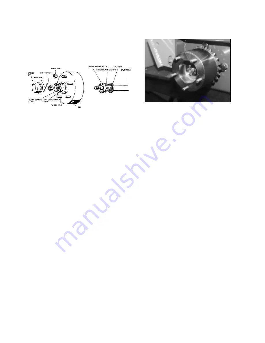
3. Carefully tap the inner cone and roller assembly
out of the inner bearing, together with the hub
grease retainer.
4. Using a suitable hammer, drive the two bearing
cups out of the hub. The inner bearing cup is
removed from the inner end of the hub and the
outer bearing cup from the outer end of the hub
(see below).
Rear Hub Clean And Inspect
1. Remove all old grease and wash parts in a
petroleum based solvent.
2. Check the bearing rollers individually by rotating
each roller in turn checking the entire surface area
for wear or pitting.
3. Inspect the entire area of the outer cup for wear or
pitting.
NOTE: Individual parts of the bearings should not be
replaced separately. If any part of a bearing is faulty,
the complete bearing must be replaced.
4. Check the threads on the end of the axle. Clean up
thread with a die nut if necessary.
Reassemble And Install Hub
1. Press the two hub bearing outer cups into position
in the hub so that the tapers are opposed to each
other, ensuring that they are completely seated.
2. Do not pack the space in the hub between the two
bearings with wheel bearing grease. Apply the
grease to the rollers of the inner bearing cone
assembly and place it in position in the hub.
3. Place a new grease retaining seal on the inner end
of the hub and tap it into position, apply a smear of
grease around the lip of the seal.
4. Apply wheel bearing grease to the inner cone and
rollers of the outer hub bearing, place the hub
assembly on the axle and position the inner cone
and rollers assembly in the end of the hub.
5. Fit castellated nut on the stub axle and while
rotating the hub, tighten the nut to a torque of 33.8
Nm (25 ft./lb.).
6. Slacken of the nut until the end float in the hub
bearing is 0.025 mm (0.001”)
7. Fit castellated nut and split pin and replace the
grease retaining cap.
NOTE: The castellated nut lock must be selectively
positioned to line up with the split pin hole.
Removal Of Front Drive Hub
1. Take out the split pin and remove the castellated
nut from the end of the hydraulic motor shaft. This
will require a socket wrench on the castellated nut
and a wrench located on the hub wheel studs to
provide opposing torque.
2. Using a hub puller, remove the hub from the
hydraulic motor’s tapered shaft. It may be
necessary to give the center threaded spindle of
the puller a sharp tap with a hammer to assist
separation of the hub from the tapered shaft.
3. Inspect the hub and motor keyways, the motor
shaft, woodruff key for signs of wear or damage.
Replacement Of Front Drive Hub
NOTE: The drive wheels are often subjected to rapid
reversals that can lead to loosening of the hub and
castellated nut on the shaft. It is essential that the
castellated nut is tightened to the correct torque value
and that a split pin is fitted and secured.
1. Insert the woodruff key into the motor shaft, align
the hub keyway with the woodruff key and push the
hub onto the motor shaft.
2. Replace the castellated nut, then using a torque
wrench, tighten the nut to a torque setting of 455
Nm (350 ft./lbs.). If the nut castellation is not
aligned with the split pin hole, tighten the nut
further until the next castellation is aligned.
3. Fit the split pin and secure it by bending one leg
down over a hexagon flat of the nut, and the other
leg over the end of the shaft.
Содержание 950001
Страница 1: ......
Страница 11: ......
Страница 15: ......
Страница 16: ......
Страница 19: ......
Страница 65: ...8 65...
Страница 66: ...8 66...


