251
Program description - Telemetry
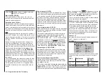
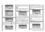
RX SERVO TEST
ALL–MIN : 1000µsec
ALL–MAX : 2000µsec
ALARM VOLT : 3.8V
ALARM TEMP–:–10°C
ALARM TEMP+: 55°C
TEST : START
CH OUT TYPE:SUMD
HD
12
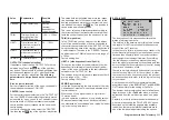
• HD („hold“)
The signals last detected as correct are “held”
at the output.
• FS
(Fail Safe)
The signals stored previously as the Fail-Safe
positions are passed to the output; see the sec-
tion entitled “Fail Safe” on page 220.
• OF (OFF)
No signals are passed to the servos during the
period of interference.
When you again press the central
SET
button of
the right-hand four-way button, the active field fi-
nally moves to Channel Select: at this point you
can determine the highest transmitter channel
which is to be included in the SUMD signal:
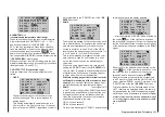
RX SERVO TEST
ALL–MIN : 1000µsec
ALL–MAX : 2000µsec
ALARM VOLT : 3.8V
ALARM TEMP–:–10°C
ALARM TEMP+: 55°C
TEST : START
CH OUT TYPE:SUMDHD
12
Note:
In most cases a value higher than “12” is not
required by devices likely to be connected to the
system.
SETTING & DATAVIEW sensor(s)
If, in addition to a “receiver”, at least one sensor is
selected in the »Telemetry« menu’s »SENSOR SE-
LECT« sub-menu (described below) then its settings
can be read in and changed in addition to the previ-
ously described receiver screens.
However, to actually gain access to this data, the
selected sensor/s must be connected to the receiver
system and this receiver system must have an active
telemetry connection.
If, as described in the next section, there is at least
one sensor activated which has the support of current
firmware, then it is possible to directly switch between
individual modules. However, if sensors with older
firmware are in use, it may be necessary to select
“etc.” instead of the direct sensor selection.
In either case, tap the
or
selection key of the left
four-way button …
RECEIVER
VARIO
etc.
… then use the same keys to select up or down for
the desired module, for example:
VARIO
GPS
RECEIVER
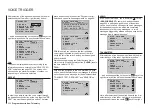
If the selected module, in this case a Vario module, is
active then on the last receiver screen (“RX SERVO
TEST”), at the top right there will also be an addi-
tional “ ” symbol pointing to the right. This symbol is
located just to the right of the left-pointing “ ” symbol
and is the visible indicator that additional display
screens can be accessed:
RX SERVO TEST
ALL–MIN : 1000µsec
ALL–MAX : 2000µsec
ALARM VOLT : 3.8V
TEST : STOP
ALARM TEMP–:–10°C
ALARM TEMP+: 55°C
CH OUT TYPE:ONCE
Now use one of the
selection keys on the left or
right four-way button to switch to the selected sen-
sor’s displays and check or change its settings as
described in the manual delivered with the sensor.
Содержание HoTT MC-16 Series
Страница 1: ...Programming Manual mc 16 mc 20 HoTT 1 en mc 16 mc 20...
Страница 27: ...27 For your notes...
Страница 53: ...53 For your notes...
Страница 61: ...61 For your notes...
Страница 65: ...65 For your notes...
Страница 71: ...71 For your notes...
Страница 103: ...103 For your notes...
Страница 107: ...107 For your notes...
Страница 111: ...111 For your notes...
Страница 133: ...133 Program description Dual Rate Expo Winged models Set the Expo values as necessary in the same man ner...
Страница 137: ...137 Program description Dual Rate Expo Helicopter models Set the Expo values as necessary in the same man ner...
Страница 155: ...155 For your notes...
Страница 165: ...165 For your notes...
Страница 201: ...201 For your notes...
Страница 229: ...229 For your notes...
Страница 231: ...231 For your notes...
Страница 261: ...261 For your notes...
Страница 265: ...265 For your notes...
Страница 301: ...301 For your notes...
Страница 327: ...327 For your notes...
Страница 328: ...328 For your notes...


