19
Rear P
anel C
onnec
tions
VERITY
®
1810 Conductivity and pH Monitor |
User’s Guide
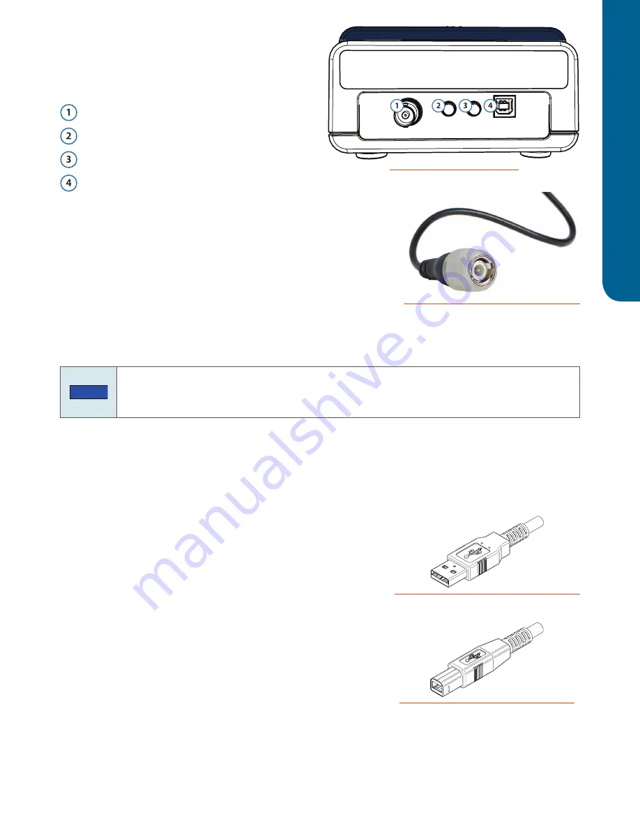
Rear Panel Connections
Refer to the diagram when making the connections
described in this section.
pH Sensor input
Analog pH output
Analog Conductivity output
USB Device port
pH Sensor
The pH sensor cable has a BNC connector.
After assembling the optional pH flow cell, connect the pH sensor
cable to the pH Sensor input, and then twist clockwise 1/4 turn to
lock. For pH flow cell assembly instructions, refer to the
appendix.
Output Channels
NOTE
If the VERITY® 1810 Conductivity and pH Monitor is part of a Gilson system, it is not necessary
to make analog output connections. In a Gilson system, make the USB connection between the
VERITY® 1810 Conductivity and pH Monitor and the PC.
The monitor has two output channels: Analog pH and Analog Conductivity. Optionally, direct output from
the monitor to an external device.
To connect an output channel, use one of the supplied cables (part number 11000023). Connect the cable to
the corresponding output port and then twist the nut to secure the connection.
To set the analog output range, refer to
USB Device
The monitor communicates with a standard PC and is powered via
USB.
To make the USB connection between the
VERITY® 1810 Conductivity and pH Monitor and the controlling
device (PC) or power source (USB hub), use the USB cable
(part number 32000012) supplied in the accessory kit. Use the
end with the “A-type” (flat) connector to connect to the controlling
device or power source and use the end with the “B-type” (square)
connector to connect to the monitor.
Figure 4
Rear Panel Diagram
Figure 5
BNC Connector on pH Sensor Cable
Figure 6
USB Cable with “A-Type” Connector
Figure 7
USB Cable with “B-Type” Connector


