


13
Installation
GGF-400, GGF-720
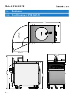
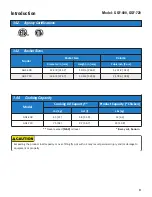
2.9.
Gas Pressure Setting & Adjustment
The following procedure is for setting the Fryer gas valve to the proper incoming gas pressure. This ensures that
the BTU output of the burners is at the correct level.
Requires a digital Manometer capable of reading Inches W.C.
(water column).
GAS TYPE
IN. WATER COLUMN [w.c.]
NATURAL
3.5”
LP
10.5”
10. Return Selector Switch and Power Switch in the
[OFF]
position.
11. Remove manometer tube; replace and tighten the Pressure
Tap Plug.
12. Replace the adjustment screw cover plug.
13. Replace the Rear Fryer Panel.
14.
Do not drain water
... Restart the Fryer as described in
Step-7
and continue set-up in
Section 2.11, Blower Vacuum
Switch Setting
.
DO NOT ever check or adjust the gas pressure without first filling the Fry Pot.
1. Fill Fry Pot with clean water to the
FULL
mark.
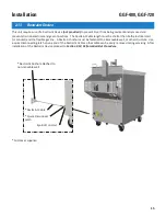
2. Remove the Lower Rear Panel from Fryer Cabinet.
3. Remove the Pressure Tap Plug from the Gas Valve. Install a
fitting appropriate for attaching a Manometer.
4. Remove the Pressure Adjustment Cover Plug on the Gas
Valve.
5. Connect a digital manometer (reading inches w.c.) to the Gas
Valve Pressure Tap and tighten.
6.
Open
the gas supply line valve. Place the Fryer Gas Shut-
Off Valve in the
[OPEN]
position.
7. Place the Power Switch in the
[ON]
position and allow
Controller to power-up. Press
[ALARM]
key to silence
alarm, then press
[START]
key. Place Selector Switch in the
[COOK]
position.
8. The burner(s) should ignite and the unit will begin heating.
9. While burner(s) are
ON
, check the Manometer pressure
reading and compare to table below. If pressure matches
for the type gas,
NO
adjustment is needed. If not, use a
screwdriver to adjust pressure ... turn to right (clockwise)
to increase, turn to left (counterclockwise) to decrease.
Observe pressure for several minutes to confirm that it
remains stable.
*
Screw Driver for
adjusting pressure
*
Manometer
with pressure
tube
Pressure
Adjustment Cover
Plug
*
Not supplied with unit
Pressure Tap Plug
Содержание GGF Series
Страница 13: ...4 Model GGF 400 GGF 720 Introduction ...
Страница 26: ...Model GGF 400 GGF 720 Overview 18 3 1 Control Panel 5 6 4 3 2 1 7 ...
Страница 28: ...20 Model GGF 400 GGF 720 Overview 3 2 Lower Cabinet 5 6 4 3 2 1 7 ...
Страница 32: ...24 Model GGF 400 GGF 720 Overview 3 4 Basket and Elevator Assembly 3 1 2 4 ...
Страница 38: ...30 Model GGF 400 GGF 720 Overview Notes ...
Страница 42: ...34 Fryer Preparation Model GGF 400 GGF 720 ...
Страница 80: ...72 Troubleshooting Model GGF 400 GGF 720 ...
Страница 84: ...76 Parts List Not shown 8 3 Front Lower Cabinet Model GGF 400 GGF 720 2 3 4 1 5 6 7 8 9 10 12 13 11 ...
Страница 86: ...78 Parts List 8 4 Rear Cabinet 2 4 1 5 9 3 6 10 11 7 8 12 Model GGF 400 GGF 720 13 14 15 16 17 18 19 ...
Страница 88: ...80 Parts List 8 5 Plumbing Model GGF 400 GGF 720 1 2 2 3 3 4 5 6 7 7 7 7 8 10 11 9 12 ...
Страница 90: ...82 Parts List 8 6 Basket Basket Cover Model GGF 400 GGF 720 1 2 3 ...
Страница 92: ...84 Parts List 8 7 Filter Pan Accessory Purchased Separately Model GGF 400 GGF 720 1 2 3 6 5 4 8 10 7 9 11 12 ...
Страница 94: ...86 Parts List Notes Model GGF 400 GGF 720 ...
Страница 95: ......


