background image

3

Model:  GGF-400, GGF-720 

Introduction

1.4.2.

Agency Certifications

Exceeding the product load capacity or over-filling fry pot with oil may result personal injury and/or damage to

equipment or property.

1.4.3 

Basket Sizes

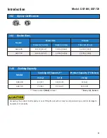
Model

Basket Size

Volume

Diameter: in [mm]

Height: in [mm]

Cubic inch [Cu m]

GGF-400

12-3/8 [314.2]

10-1/4 [260.4]

1,231.8 [.020]

GGF-720

14-3/4 [374.7]

12-3/4 [323.9]

2,178.6 [.036] 

** 

Never exceed 

[MAX]

oil level

* 8-way cut, bone-in

1.4.4

Cooking Capacity

Model

Cooking Oil Capacity**

Product Capacity (*Chicken)

Lbs [kg]

Gal [l]

Lbs [kg]

GGF-400

45 [21]

5.8 [21.9]

14 [6.3]

GGF-720

75 [34]

9.7 [36.7]

24 [10.8] 

Содержание GGF Series

Страница 1: ...Mar 2020 Rev G Operations Service Manual GGF Series Fryer ISO 9001 Registered Committed to Quality 2750 Gunter Park Drive West Montgomery AL 36109 USA Toll Free 800 554 4537 USA Canada Only Other 334 272 1457 Fax 334 239 4117 Website www gfse com Email services gfse com ...

Страница 2: ...an adequate room air exchange rate to prevent accummulation of combustion flue gases carbon monoxide CO2 Improper installation and use can cause personal injury even death Read the installation operating and maintenance instructions thoroughly before installing and attempting to operate or service this appliance FOR YOUR SAFETY DO NOT store or use flammable liquids or materials or those which may ...

Страница 3: ...s requested Giles will dispatch factory authorized service representatives to inspect repair recondition or replace units of its manufacture with such labor being rendered without cost to owner for twenty four 24 months from the date of installation Otherwise service including labor and transportation charges or other expenses in connection with the removal or installation of any part or parts sup...

Страница 4: ... 8 2 5 2 Fuel Gas Specifications 8 2 6 Electrical Connections 9 2 7 Gas Line Connection 9 2 7 1 Typical Gas Supply Line Connection 10 2 8 Gas Orifices Informations Replacement Procedure 12 2 9 Gas Pressure Setting and Adjustment 13 2 10 Blower Vacuum Switch Setting and Adjustment 14 2 11 Restraint Device 15 3 Overview 17 3 1 Control Panel 18 3 2 Lower Cabinet 20 3 3 Filter Pan Assembly 22 3 4 Bask...

Страница 5: ...ser Settings Access Edit 47 5 1 8 PASSWORD Protection 48 5 1 9 Start up Procedure 48 5 1 10 Controller Errors and Alarms 49 5 1 10 1 Resolving Controller Errors and Alarms 50 5 2 Cooking Procedure 50 5 3 Filtering Cooking Oil 55 5 4 Removing Waste Oil from Fryer 59 5 5 Normal Shutdown 62 5 6 Emergency Shutdown 62 6 Cleaning 63 6 1 Boil Out Procedure Cleaning the Fry Pot 63 6 2 Cleaning the Filter ...

Страница 6: ...rt symbol and key words such as DANGER WARNING or CAUTION Alert information precedes the tasks to which it applies Suggested recommended or other noteworthy information is identified as NOTES or will be noted as IMPORTANT Additionally certain words are used to indicate a specific meaning or to add emphasis as follows Shall understood to be mandatory Should understood to be advisory May understood ...

Страница 7: ...t installation complies with all electrical requirements and codes Appliance must be installed and electrically grounded in accordance with local code or in the absence of local code in accordance with the National Electrical Code NFPA 70 Improper grounding may result in electrical shock to users Always refer to local electrical code to ensure proper grounding of this or any other electrical equip...

Страница 8: ...res and instructions in order to avoid equipment damage or malfunction To avoid personal injury it is recommended that thermal hand protection gloves or mitts be worn while tended the appliance Certain parts of the Fryer will become very HOT during operation temperatures inside cabinet may exceed 150 F 65 5 C Exercise caution when operating and cleaning Placing foods containing excessive moisture ...

Страница 9: ...howed any signs of damage you should immediately inspect the appliance and associated accessories and notify the freight carrier of any and all damages Comply with all appropriate state and or local heath regulations regarding cleaning and sanitization of foodservice equipment ...

Страница 10: ...ides for up to fifty 50 programmable menu item cooking presets Monitors fryer status displays operational instructions warnings and errors DRAIN OPEN LOW OIL LEVEL MAX ELEMENT TEMP etc Features BOIL OUT program COOL MODE FORCE FILTER control available password protection multiple languages and enhanced safety Dual Burner system Model GGF 720 only Unique dual burner system delivers maximum BTU s wh...

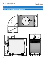
Страница 11: ...2 Model GGF 400 GGF 720 Introduction 1 4 Specifications 1 4 1 Overall Dimensions GGF 400 GGF 720 44 7 16 1129mm 36 5 8 931mm 5 1 4 133 99mm 1 1 5 21 7 8 556mm DOOR SWING REVERSIBLE 42 11 32 24 3 8 619mm ...

Страница 12: ...r property 1 4 3 Basket Sizes Model Basket Size Volume Diameter in mm Height in mm Cubic inch Cu m GGF 400 12 3 8 314 2 10 1 4 260 4 1 231 8 020 GGF 720 14 3 4 374 7 12 3 4 323 9 2 178 6 036 Never exceed MAX oil level 8 way cut bone in 1 4 4 Cooking Capacity Model Cooking Oil Capacity Product Capacity Chicken Lbs kg Gal l Lbs kg GGF 400 45 21 5 8 21 9 14 6 3 GGF 720 75 34 9 7 36 7 24 10 8 ...

Страница 13: ...4 Model GGF 400 GGF 720 Introduction ...

Страница 14: ... Gas Technician Only 2 11 Correct blower vacuum switch setting Qualified Gas Technician Only 2 12 Filter Pump operating 2 13 Restraint device installed 2 14 Performed Boil Out procedure 2 15 Cleaned Filter Pan Various installation tasks described in this Manual MUST be performed only by a Licensed Electrician and a Qualified Gas Appliance Technician NOTE This appliance must be electrically grounde...

Страница 15: ... 3 Verify that electrical power available in the intended location is the proper voltage and amp rating adequate to power the appliance 4 A stable fuel gas supply must be available at the intended location 1 2 supply line fitted with service shutoff valve is required 5 Be sure unit is installed in a stable position and will not unintentionally move Unit has locking brakes on front casters be sure ...

Страница 16: ...HES mm GGF 400 GGF 720 R 24 3 8 619mm 44 7 16 1129mm 36 5 8 931mm 5 1 4 133 99mm 42 25 32 1086 51 REGULATOR W 1 2 NPT GAS LINE CONNECTION COMBUSTIBLES NON COMBUSTIBLES 18 457 2 4 101 6 4 101 6 18 457 2 18 457 2 4 101 6 NON COMBUSTIBLES COMBUSTIBLES 6 POWER CORD INCLUDED ...

Страница 17: ...ons reference CSA B149 1 or 2 Installation Codes for Gas Burning Appliances and Equipment This appliance is to be installed used and maintained in accordance with the Standard for Ventilation Control Fire Protection of Commercial Cooking Operations NFPA 96 Consult a professional certified HVAC company for assistance in designing and specifying a ventilation hood system for this unit NOTE Guideline...

Страница 18: ...tion gases produced by this appliance must be vented to the outside in accordance with the prevailing National Fuel Gas Code ANSI Z223 1 and terminate with a UL listed outside vent terminal For Canadian installations reference CSA B149 1 or 2 Installation Codes for Gas Burning Appliances and Equipment Quick disconnect devices must comply with the Standard for Quick Disconnect Devices for Use with ...

Страница 19: ...ed from the incoming gas supply line by closing the fryer Gas Shutoff Valve during any testing of the piping at test pressures equal to or less than 1 2 psi 3 5kPa 1 Check pressure of the incoming gas supply and compare to Table 2 5 2 If necessary install a secondary pressure regulator on the supply line to regulate supply pressure to a maximum of 13 85 W C 3 45 kPa 2 Install an appropriate Quick ...

Страница 20: ... as shown in Table 5 2 2 This regulator is rated for max input pressure of 13 85 W C 3 45 kPa If supply line pressure exceeds this maximum a secondary regulator must be installed in the supply line upstream of the installed regulator to maintain pressure at or below the maximum rating 2 7 1 Typical Gas Supply Line Connection continued ...

Страница 21: ... Manifold 6 Remove replace Orifice in the Manifold with the proper size See charts below 7 Re install Gas Manifold with installed orifice reconnect gas line and replace Panel Guard Proceed to Section 2 10 Gas Pressure Setting and Adjustment IMPORTANT Fryer is shipped with factory installed standard gas Orifices for operation with Natural Gas at 0 3 000 feet AMSL or LP Gas at 0 4 000 feet AMSL Chan...

Страница 22: ...net 3 Remove the Pressure Tap Plug from the Gas Valve Install a fitting appropriate for attaching a Manometer 4 Remove the Pressure Adjustment Cover Plug on the Gas Valve 5 Connect a digital manometer reading inches w c to the Gas Valve Pressure Tap and tighten 6 Open the gas supply line valve Place the Fryer Gas Shut Off Valve in the OPEN position 7 Place the Power Switch in the ON position and a...

Страница 23: ...ng is unblocked the fan should restart and burner s should relight If this occurs the setting is satisfactory go to Step 8 If burner s fail to shutdown the Blower Vacuum Switch must be adjusted as follows 4 Shutdown Fryer 5 Remove retaining screws at the top of the Control Panel and lower panel 6 Locate pressure switch on left side of the Control Box remove plastic cover if still in place 7 Slowly...

Страница 24: ...r conduit and the flexible gas line A Restraint Anchor must be fastened to a immovable wall or other structure Use a quick disconnecting latch on one end of the Restraint Cable so that cable can be easily removed during servicing After installation of the Restraint Device proceed to Section 2 13 Perform Boil Out Procedure 2 11 Restraint Device Restraint Anchor attached to non movable wall Restrain...

Страница 25: ...re 3 3 Lower Cabinet Figure 3 2 Basket Elevator Assembly Section 3 4 The following section provides a brief overview of components features and accessories associated with the Giles GGF Series Fryer Please review this section completely before attempting to use the appliance 3 Overview ...

Страница 26: ...Model GGF 400 GGF 720 Overview 18 3 1 Control Panel 5 6 4 3 2 1 7 ...

Страница 27: ...rs Fryer operation and displays alarm conditions and various operational instructions 4 Power Indicator Light Green light is illuminated whenever the appliance Power Switch is in the ON position 5 Heat Indicator Light Amber light illuminates whenever Fryer burner s are ON and heating the cooking oil Cycles ON OFF while cooking as the Controller regulates oil temperature to setpoint 6 Hi Limit Indi...

Страница 28: ...20 Model GGF 400 GGF 720 Overview 3 2 Lower Cabinet 5 6 4 3 2 1 7 ...

Страница 29: ...E Fryer will NOT heat unless Drain Valve is completely closed 4 Filter Pan Quick disconnect Connects the Filter Pan hose to the Oil Filtration System 5 Fryer Filter Pan Collects used cooking oil drained from the Fry Pot Contains media for filtering oil See Section 3 3 for more detail 6 Filter Pan Cover Helps to contain splash and splatter as oil is being drained into the Filter Pan Helps keep floo...

Страница 30: ...22 Model GGF 400 GGF 720 Overview 3 3 Filter Pan Assembly Non standard Sold separately Not Included 5 6 3 1 2 4 7 ...

Страница 31: ... Filter Pan Quick disconnect Hose Connects the Filter Pan to the Fryer oil filtration system This hose must be disconnected before the Filter Pan can be removed 6 Filter Pan Collects used cooking oil for filtering contains filter media which filters and reconditions oil during the filter cycle The Filter Pan features casters and is removable for cleaning and changing of filter media Features a per...

Страница 32: ...24 Model GGF 400 GGF 720 Overview 3 4 Basket and Elevator Assembly 3 1 2 4 ...

Страница 33: ...ot cooking oil from splashing or splattering out of Pot 2 Basket Carrier Holds Fry Basket as it is lower and raised by the Auto Basket Lift 3 Basket Contains product while cooking 4 Auto Basket Lift Lowers Basket into cooking oil then automatically raises cooked product out of hot oil at end of cooking time 3 4 Basket and Elevator Assembly ...

Страница 34: ...nger Ring and pot wall Stirring Utensil P N 77775 Use to stir cooking oil and product in the pot as it is cooked Pot Brush P N 71100 Heat resistant brush for clean Fry Pot and Heat Exchanger surfaces Crumb Shovel P N 30059 Use to remove filter sediment from Filter Pan 26 Model GGF 400 GGF 720 Overview 3 5 Accessories Included ...

Страница 35: ...F 400 GGF 720 Overview Part Description Part Number Function Discharge Hose Assembly P N 33667 Use for removing liquid shortening from unit NOTE DO NOT USE TO WASH DOWN THE COOK VAT 27 3 5 Accessories Included ...

Страница 36: ...ction Filter Paper P N 60810 Filter media to be use in Filter Pan fo filtering cooking oil Filter Powder P N 72004 Filter aid for use when filtering cooking helps recondition oil by removing soluble impurities Fryer Boil Out P N 72003 Fry pot cleaning agent add to water during boil out procedure ...

Страница 37: ...oil disposal container with a capacity of 80 lbs of liquid shortening Intended to handle only warm filtered oil containing no crumbs or debris Filter Pan Crumb Screen P N 39246 Filter Pan insert helps prevent larger crumb particles or cooking debris from getting into the Filter Pan 3 6 Accessories Not Included ...

Страница 38: ...30 Model GGF 400 GGF 720 Overview Notes ...

Страница 39: ...ting Fryer Giles takes pride in quality of workmanship Every effort has been made to ensure that new equipment is in perfect operating condition when received Every unit must pass rigorous quality control testing prior to shipment and to further ensure that it meets your expectations it is recommended that this operational checkout and preparation be performed prior to using the fryer for the firs...

Страница 40: ...r does not ignite within an allowed time fryer enters FLAME FAIL error Return Selector Switch to OFF wait 10 seconds and try again 4 After ignition the surface of the heat exchanger should dry quickly within approximately 15 seconds and noticeable heat should be felt rising from the pot indicating acceptable operation 4 If burners do not light after two 2 attempts or appear not to be heating refer...

Страница 41: ...hipping and any residue which may remain from manufacturing processes See Section 6 1 Boil Out Procedure After completion proceed to Section 4 6 3 1 2 Thoroughly clean the filter pan to remove dirt debris that may have accumulated during shipment or residue remaining from manufacturing processes See Section 6 2 Cleaning the Filter Pan and Replacing Filter Paper after Boil Out Wash accessory items ...

Страница 42: ...34 Fryer Preparation Model GGF 400 GGF 720 ...

Страница 43: ... sometimes cover cooking vats pots are not designed to and WILL NOT support the weight of a person Failure to comply with WARNING notices could result in serious injury even death damage to equipment and or property and will void the factory warranty Be sure the fryer is positioned in a stable safe location with the casters in the locked position Consult an electrician to be certain that all elect...

Страница 44: ...ettings and to edit preset Menu Item cooking parameters The 2 4 6 8 keys are also used as ARROW KEYS for operating Basket Lifts if installed selecting timer navigating lists moving cursor for editing etc 2 8 UP DOWN 4 6 LEFT RIGHT The keys will illuminate to indicate when they are active as ARROW KEYS START Function key used to start cook cycles select items save settings and exit editing etc CLEA...

Страница 45: ...Key Press this key to set the cooking oil temperature setpoint Pressing this key twice 2x will display ACTUAL OIL TEMPERATURE on the Lower Display for approximately 20 seconds Press this key during preheat phase to enter BOIL OUT mode Temperature setpoint and time changes to the BOIL TEMP and BOIL OUT TIME as specified in USER SETTINGS see Section 5 1 7 Access Edit User Settings Default 200 F 30 m...

Страница 46: ... performance Upon reaching setpoint the alarm sounds again and the Upper Display reads ALARM SETPOINT REACHED Pressing the ALARM key places the Fryer in READY state READY STATE Fryer is ready for cooking The current cooking temperature setpoint will be shown on the Lower Display and the last used cooking parameters preset or manual inputs are shown on the Upper Display While in PREHEAT or READY st...

Страница 47: ...amber HEAT indicator on the Control panel should turn ON burners ignite and oil begins to heat If oil temperature is already equal to or greater than the entered setpoint an alarm sounds and the message STIR OIL is displayed Press the ALARM key and stir If oil remains at setpoint when oil returns to setpoint alarm sounds again and message SETPOINT REACHED is display Press ALARM key Controller ente...

Страница 48: ... Temperature setpoint is automatically changed to this setting when the Preset is selected for use STIR OVERRIDE Users may wish to override the Controller global STIR ALARM setting in USER SETTINGS for certain menu items Factory default NORMAL use global setting FISH FILTER To prevent flavor transfer establishments cooking seafood products may wish to force an oil filtering after only one 1 batch ...

Страница 49: ...ting NAME Method 1 Enter NAME letter by letter Select the NAME as shown on left A flashing cursor is positioned at 1st letter Use arrow keys 2 8 to scroll through alphabet Character at cursor changes while scrolling stop at desired character Use arrow key 6 right to move cursor to next character and repeat When finished editing press START to Save OR press CLEAR to Cancel and Exit without saving E...

Страница 50: ...ct input After entering new TIME value press START to Save OR Press CLEAR to exit without Saving Scroll to and select TIME for edit as shown on previous page Current temp setting will be displayed Use keypad to enter new cooking TEMP setpoint F 335 335 F While entering temp CLEAR key backspaces to erase an incorrect input After entering new TEMP value press START to Save OR Press CLEAR to exit wit...

Страница 51: ...pointing to STIR Press the START key to toggle between the available options stop at desired setting To minimize potential for flavor transfer establishments cooking seafood items may wish to force operators to filter oil after only one 1 batch is cooked When FISH FILTER is set to ON the unit will enter FILTER MODE after completing 1 load of the specific item If FORCE FILTER SNOOZE is set to ON in...

Страница 52: ...enu Item information is shown on the Upper Display After selecting the menu preset place Selector Switch in COOK position NOTE Basket Lift is inoperable while fryer is in PREHEAT mode Lift is enabled when setpoint is reached and fryer enters READY state Before selecting a menu preset be sure that Selector Switch on control panel is in the OFF position and that pot is filled with cooking oil Direct...

Страница 53: ...ring helps to promote even cooking and prevent sticking This feature must be enabled in User Settings Section 5 1 7 and the parameter set STIR ALARM amount of elapsed time when the alarm sounds e g if STIR ALARM 60 then during a 10 min cook cycle the alarm will sound after 6 mins of time have elapsed Factory set default STIR ALARM ENABLE ON STIR ALARM 62 The menu item STIR OVERRIDE setting overrid...

Страница 54: ...ture is reached COOL MODE is an energy saving feature that changes oil temperature setpoint to a lower valve Places Fryer into an idle standby state during periods of inactivity Enter COOL MODE by pressing the COOL key The temperature setpoint changes to the COOL TEMP setting specified in User Settings see Section 5 1 7 Edit User Settings Factory set default 275 F The setting can be edited in the ...

Страница 55: ... Temperature of the COOL mode 200 F to 350 F 275 F BOIL TEMP Temperature of the BOIL OUT mode 185 F to 208 F 200 F FILTER RESET Temperature that allows exiting of filter mode 200 F to 325 F 290 F BOIL OUT TIME Time in minutes for BOIL OUT mode 1 to 45 minutes 30 STIR ALARM ENABLE If enabled allows the stir alarm to come on during a cook cycle ON OFF ON STIR ALARM When STIR ALARM is ON the alarm wi...

Страница 56: ... Selector Switch in the COOK position The draft fan starts running and burner will ignite If burner does not ignite after the allowed amount of time the red Flame Fail Light will turn ON and the fryer gas valve closes If this occurs return Selector Switch to OFF wait 2 3 minutes to allow accumulated gas to dissipate then try again 2 1 3 4 5 IMPORTANT If the appliance continues failing to ignite re...

Страница 57: ...ician generally required ER17 ADD LEVEL PROBE Error Problem with add level probe at vat ADD mark Fryer without this probe should have ELMT ADD DIFF ENABLE setting OFF in Factory Settings Probe cannot be bypassed Service technician generally required ER19 MAX ELEMENT TEMP Error The maximum heating element temperature has been exceeded This is a safety device NEVER bypass this Probe ER25 GUARD BAND ...

Страница 58: ...ed until the condition is corrected The temperature differential between the ADD Level Probe and the probe on the Heat Exchanger Ring exceeds the acceptable value indicating a low oil level Low level greatly increases the possibility of oil fire Press the ALARM key to silence alarm tone and place Selector Switch in OFF position Allow the Fryer to adequately cool and then add oil to raise level to ...

Страница 59: ...he ADD mark As cooking temperature is reach expansion should bring oil level to near the FULL mark 7 Set Controller for cooking Use keypad to manually set temperature and cook time see Section 5 1 3 Manually Setting a Temperature Cook Time OR select a desired Menu Item Preset see Section 5 1 4 2 Selecting a Menu Preset for Cooking Controller enters PREHEAT mode current cook settings are shown on t...

Страница 60: ...int temperature heating will shutdown and HEAT light will turn OFF 11 An alarm sounds and the message ALARM STIR OIL is displayed on the Upper Display Press the ALARM key and vigorously stir oil There is a 10 second delay and if oil temperature drops below setpoint while stirring controller returns to PREHEAT A second alarm sounds when setpoint is reached again and message ALARM SETPOINT REACHED i...

Страница 61: ...has been lowered into the hot cooking oil To manually lower basket before loading press BASKET key then press 8 on keypad to lower basket NOTE Basket Lift will not operate unless controller indicates READY Load basket while in UP position Basket automatically lowers when cooking cycle is started Controller must be in the READY state before the cooking cycle will start Press the START key If in up ...

Страница 62: ...t amount of programmed cook time has elapsed The Upper Display reads ALARM STIR Press the ALARM key to silence alarm Wear oven mitts or other thermal protection remove the basket cover and stir agitate the cooking product with the provided stirring utensil to separate pieces Replace the cover 18 At the end of the cooking cycle the basket with cooked product will automatically be raised from the oi...

Страница 63: ...ook cycle until filtering is performed FILTER COUNT 1 to 20 Factory default 4 The number of cook cycles that can be performed before fryer enters FILTER MODE FORCE FILTER SNOOZE ON or OFF Factory default OFF Effective only when FORCE FILTER is ON ON Allows operator to cook one 1 additional load of product after FILTER COUNT has been reached before unit enters FILTER MODE and is disabled OFF No add...

Страница 64: ...r Pan Hose push in white slip ring while inserting brass fitting into connector Ensure that hose fit is tight and secure 4 5 6 The next steps require that cooking oil be drained into the filter pan thus exposing the heating elements Fryer is equipped with safety interlocks which disable heating elements anytime the drain valve is opened As further safeguard to reduce risk of oil fire always place ...

Страница 65: ...an heat exchanger as described below can result in excessive carbon build up between the pot wall and heat exchanger ring which can lead to premature failure of the pot and heat system and will void the factory warranty EXTREMELY IMPORTANT Each time fryer oil is filtered it is important that the front and back of the heat exchanger be cleaned thoroughly Use the heat resistant utility brush to scru...

Страница 66: ...t a minimum filter pan should be thoroughly cleaned and media refreshed DAILY see Section 6 2 Cleaning Filter Pan Replacing Filter Media 16 Replace cover and reinstall filter pan 17 To continue cooking See Section 5 2 Cooking Procedure To discontinue cooking See Section 5 5 Normal Shutdown 11 8 9 5 3 Filtering Cooking Oil continued IMPORTANT If FORCE FILTER is ON the fryer will not exit FILTER MOD...

Страница 67: ...with filter media is in place and the Filter Pan Hose is properly connected to fryer 4 Slowly turn the Drain Valve Handle to the OPEN position fully up to stop and allow the pot to completely drain DO NOT attempt to pump cold congealed oil The filter pump can clog and be damaged Oil should be at a minimum of 200 F 93 C before pumping This section explains the procedure for removal and disposal of ...

Страница 68: ...ddy is depicted not included 8 Place the Oil Diverter Valve in the HOSE position right to stop 9 Wear some type of thermal protective gear if holding the Discharge Hose is necessary it will become very hot while pumping oil Set the Selector Switch to the FILTER PUMP position The waste oil is pumped into the disposal container IMPORTANT Always attend this process to avoid the possibility of hose fa...

Страница 69: ...d promptly See Section 6 1 Boil Out Procedure DO NOT allow oil residue to remain in the pot for an extended period of time without boiling out or refilling with fresh oil as over time it will become more difficult to remove and eventually can lead to an undesireable build up that may negatively impact fryer performance and food quality At a minimum if boil out must be postponed while oil is still ...

Страница 70: ...oward front of fryer 4 If required to disconnect all supply power from the appliance unplug power cord from receptacle or turn OFF circuit breaker in the electrical panel supplying power to unit 5 If required turn off main gas supply line valve In case of emergency remove power to the unit by turning off the facility circuit breaker and shut off main gas supply line 3 1 2 5 5 Normal Fryer Shutdown...

Страница 71: ...uipment or property damage and void the warranty The Boil Out process does not require a rolling boil nevertheless DO NOT leave fryer unattended during the procedure It should be carefully monitored for accidental overflow which can result in serious equipment damage The boil out solution and fryer will become very HOT always wear thermal hand protection when draining and cleaning as well as other...

Страница 72: ...to run completely These values can be changed in User Settings Section 5 1 7 8 When boil out cycle time expires a DONE COOKING alarm sounds place both Selector Switch and Power Switch in the OFF position 6 4 3 5 NOTE As a safeguard when the boil out cycle ends the controller temperature setpoint automatically changes to 50 F Before cooking activities can resume a menu item preset must be re select...

Страница 73: ...d dried before adding fresh cooking oil Give particular attention to the drain valve as residual water will accumulate in the space above the valve Water in the pot will cause boiling and foaming of cooking oil when heated which could result in overflow 6 1 Boil Out Procedure continued Failure to routinely clean the area of the pot shown below in order to avoid excessive carbon build up between th...

Страница 74: ... thoroughly 6 Grasp edge of soiled sheet of filter paper carefully roll it up taking care not to allow filter debris to fall through perforated screen in the pan bottom and discard 7 Clean filter pan rinse thoroughly and dry completely Be certain to drain all water from the filter pan hoses 8 Reassemble filter pan using one 1 fresh sheet of filter paper proper size 15 1 2 x 21 3 8 Close all lockin...

Страница 75: ...supply voltage Connect to proper power supply FRYER WILL NOT HEAT POWER light ON HEAT light not ON no alarm sounding A Selector Switch not in COOK position Place Selector Switch in COOK position FRYER WILL NOT HEAT POWER light is ON Selector Switch is in COOK position HEAT light is OFF A Temp setpoint is lower than actual oil temperature Check setting oil temp correct if needed or if temp is satis...

Страница 76: ...ect Install proper orifice F Faulty Gas Control Valve Replace Gas Valve G Faulty Ignitor Replace Ignitor H Faulty Ignition Module Replace Ignition Module I Faulty Gas Valve Transformer Check replace Transformer J Dirty burner Clean burner FRYER WILL NOT HEAT POWER light ON HEAT light not ON Alarm sounding or Error Message displayed A Drain Valve open Close valve completely B Loose wiring Check rep...

Страница 77: ...N A Improper cooking procedure Consult Operations Manual for proper operating procedures B Burner system problem Inspect system repair C Incorrect gas pressure See Sections 2 8 Gas Line Connection and 2 10 Gas Pressure Setting Adjustment FRYER HEATS SLOW HEAT light OFF ON CONTINUOUSLY Short cycling A Low voltage Check incoming power supply and connections B Variable temp sensor is touching or too ...

Страница 78: ...r position B Air leak in system Check hoses and connections C Faulty pump motor Inspect replace if needed D Pump head clogged or bound Remove head cover clean out pump as needed E Diverter Valve not in FRYER position Place valve handle in proper position F Oil has congealed inside pump head Run clean hot oil through system G Oil is too cool to be pumped efficiently below 200 F 93 C Remove filter p...

Страница 79: ...ler are faulty Perform key function diagnostics C Cook cycle is running Cancel running cycle D Elevator micro switches out of adjustment Adjust switches E Oil temp has not yet reached setpoint during PREHEAT Allow oil to heat to setpoint and fryer to enter READY state F Basket Lift motor is faulty Inspect replace if needed G Controller is faulty Check replace if needed I Loose wiring in lift contr...

Страница 80: ...72 Troubleshooting Model GGF 400 GGF 720 ...

Страница 81: ...ted inside the Fryer cabinet or on the rear cabinet panel IN THE UNITED STATES CANADA call 800 554 4537 ALL OTHERS call 334 272 1457 Normal business hours are 8 00 AM to 5 00 PM Central Time calls are handled by an automated answering system Please follow the recorded prompts to reach appropriate support If necessary after hours leave voicemail message a representative should respond within 30 min...

Страница 82: ...74 Parts List 8 2 Front Header Control Panel Model GGF 400 GGF 720 FRONT HEADER PANEL 2 3 4 Not Shown 5 6 1 7 8 9 10 11 12 13 14 14 14 15 17 16 18 FRONT CONTROL PANEL ...

Страница 83: ...AMP SC 15 8 23782 1 SONALERT 9 40877 1 FITTING 1 4 BARBED 90 EL NYL 1 8 NPT 10 21423 1 RELAY POWER SWITCH 30A 2 5HP 11 20403 1 INDICATOR LIGHT GREEN 12 20429 1 INDICATOR LIGHT AMBER LED 28V 13 20428 2 INDICATOR LIGHT RED LED 28V 14 20307 4 RETAINING CLIP INDICATOR LIGHT 15 21374 1 COMPUTER CONTROLLER CC10 16 21189 1 SWITCH ROCKER ON OFF ON 250V 20A S P 17 21190 1 SWITCH ROCKER ON OFF 250V 20A D P ...

Страница 84: ...76 Parts List Not shown 8 3 Front Lower Cabinet Model GGF 400 GGF 720 2 3 4 1 5 6 7 8 9 10 12 13 11 ...

Страница 85: ...SSY GGF 4 21386 2 LIMIT SWITCH DRAIN SPDT 5 41699 1 COUPLING QUICK DISCONNECT FEMALE 6 38845 1 DOOR WELD ASSY GGF 7 91823 1 FILTER PAN ASSEMBLY GGF 8 95555 1 FILTER PAN COVER GEF GGF 9 40851 1 CATCH MAGNET DOOR SNAP IN 2 3IN 10 40806 2 CASTER 5 000 RIGID W BRAKE GEF 11 45876 1 DRAIN VALVE 1 1 2 NPT GGF 12 90943 2 DOOR HINGE PIN WELD ASSY GGF 13 45755 1 VALVE 3 WAY 1 2 NPT NICKEL PLATED 8 3 Front L...

Страница 86: ...78 Parts List 8 4 Rear Cabinet 2 4 1 5 9 3 6 10 11 7 8 12 Model GGF 400 GGF 720 13 14 15 16 17 18 19 ...

Страница 87: ...SHAFT CYLINDER ASSY ELEVATOR 12 90882 1 FLUE PIPE ALL GGF 400 GGF 720 LP 91493 1 FLUE PIPE GGF 720 NAT 13 46727 1 or 2 GAS ORIFICE MANIFOLD GGF 400 1 GGF 720 2 14 40920 1 or 2 90 FITTING BRASS 3 8 CMPRSS to 1 4 NPT GGF 400 1 GGF 720 2 15 40912 1 GAS LINE 3 8 OD X 10 1 4 CMPRSS w NUTS GGF 400 GGF 720 16 40911 1 GAS LINE 3 8 0D X 7 1 8 CMORSS w NUTS GGF 720 ONLY 17 40890 1 SOLENOID VALVE N C 24VAC 2...

Страница 88: ...80 Parts List 8 5 Plumbing Model GGF 400 GGF 720 1 2 2 3 3 4 5 6 7 7 7 7 8 10 11 9 12 ...

Страница 89: ... 43850 2 NIPPLE 1 2 CLOSE 4 41900 1 QUICK DISCONNECT 1 2 5 45755 1 3 WAY VALVE 6 41699 1 COUPLING FEMALE QUICK DISCONNECT 7 40889 4 ADAPTER 1 2 COMPRESSION X 1 2 PIPE THREAD 8 35108 1 VALVE HANDLE DIVERTER VALVE 9 10098 1 SET SCREW 1 4 20 X 1 4 SOC HD CUP PT 10 40909 1 HOSE CORRUGATED SS 1 2 ID X 15 11 41119 1 HOSE CORRUGATED SS 1 2 ID X 24 12 10524 10 WASHER 843 X 1 190 X 036 THK 8 5 Plumbing ...

Страница 90: ...82 Parts List 8 6 Basket Basket Cover Model GGF 400 GGF 720 1 2 3 ...

Страница 91: ...Part Number Qty Description 1 33883 1 BASKET COVER ASSY GGF 720 33884 1 BASKET COVER ASSY GGF 400 2 38930 1 BASKET CARRIER ASSY GGF 720 39165 1 BASKET CARRIER ASSY GGF 400 3 91811 1 BASKET GGF 720 33718 1 BASKET GGF 400 8 6 Basket Basket Cover ...

Страница 92: ...84 Parts List 8 7 Filter Pan Accessory Purchased Separately Model GGF 400 GGF 720 1 2 3 6 5 4 8 10 7 9 11 12 ...

Страница 93: ... DOWN FRAME 5 38841 4 HANDLE SUPPORT FRAME FILTER PAN GGF 6 44150 1 FITTING BRASS MALE 1 2NPT QUICK DISCONNECT 7 38830 1 HOLD DOWN FRAME WELD ASSY 8 60810 1 PAPER FILTER 21 375 X 15 500 GGF 9 39246 1 CRUMB SCREEN FILTER PAN GGF 10 40956 1 HOSE 1 2NPT X 11 500 11 42250 1 ELL BLACK STREET 1 2 90 DEG 12 42200 1 ELL BLACK 1 2 90 DEG Accessory Purchased Separately DOES NOT include Item 9 Crumb Screen 8...

Страница 94: ...86 Parts List Notes Model GGF 400 GGF 720 ...

Страница 95: ......

Страница 96: ...O Box 210247 2750 Gunter Park Drive West Montgomery Al 36121 0247 USA Phone 334 272 1457 Toll Free 800 554 4537 USA Canada Only FAX 334 239 4117 www gfse com Form No 65474 Rel Jan 2009 Rev Mar 2020 Rev G ...

Отзывы: