background image

43

URB 60 - Installation & Operating Manual - 

819699-00

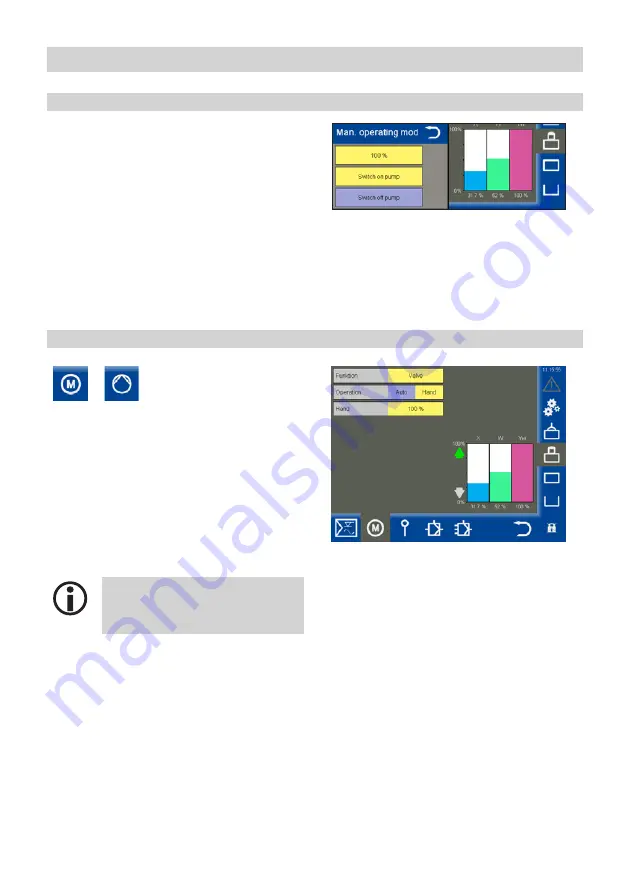
Tap “Hand” (Manual) to enable manual control.
Then, in the list box, set the control point for man-
ual operation and switch the pump on or off.

Configuring the level controller

Setting manual control or the control point for manual pump operation

Switching actuator operation between automatic and manual

 or 


Open the 

 menu.

One of the icons is displayed, depending on which 
function is enabled.

Description of parameters:

Operation (Auto/Manual)

In manual mode, the drive can be operated 
manually.

Hand (= Manual)

Set the drive or valve as desired.


The system automatically switches 
back to automatic mode when you 
close this window.

Содержание URB 60

Страница 1: ...Original Installation Operating Manual Visual Display and Operating Unit URB 60 819699 00 E N English ...

Страница 2: ... 14 Technical data 15 Factory settings 16 Name plate identification 17 Dimensions of the URB 60 18 Installation instructions 18 Ports and sockets on the URB 60 19 Connecting the supply voltage 20 Connecting the CAN bus system 20 Bus line cable length and cross section 20 Important notes on connecting the CAN bus system 21 Pin assignment of the CAN bus connector and coupling for non pre wired contr...

Страница 3: ... the control point for manual pump operation 43 Switching actuator operation between automatic and manual 43 Valve calibration in manual mode when a feedback potentiometer is connected to the NRR 2 60 44 Calibrating the boiler level 45 Setting the level controller 46 Guide to setting control parameters 46 Setting the level controller for 3 component control 47 Configuring the conductivity controll...

Страница 4: ...des 59 Fault codes for the URS 60 URS 61 safety control unit 59 Fault codes for the NRR 2 60 NRR 2 61 level controller LRR 1 60 conductivity controller and URW 60 universal converter 60 Common faults during use 62 What to do in the event of system malfunctions 62 Checking installation and function 62 Data exchange via Modbus TCP 63 Taking out of service 63 Disposal 63 Returning decontaminated equi...

Страница 5: ...ht All rights reserved Any misuse particularly reproduction and dissemination to third parties is not permit ted The General Terms Conditions of GESTRA AG apply Scope of delivery Product package 1 x URB 60 visual display and operating unit 6 x retaining clips 1 x power supply connector 1 x URB 60 data cable with integrated 120 Ω terminating resistor 1 x Eaton Installation Manual MM YY IL048007ZU 1...

Страница 6: ...instructions Please also read the instructions for use of any accessories The Installation Operating Manual is part of the equipment package Keep it in an easily accessible location Availability of this Installation Operating Manual Make sure this Installation Operating Manual is always available to the operator If you pass on or sell the equipment to a third party please also hand over the Instal...

Страница 7: ...uation that results in death or serious injury WARNING Warning of a dangerous situation that may possibly result in death or serious injury CAUTION Warning of a situation that may result in minor or moderate injury ATTENTION Warning of a situation that results in damage to property or the environment ...

Страница 8: ...liability and severe damage to steam generating units and pipes To keep the TDS concentration within admissible limits a certain portion of boiler water must be removed continuously and or periodically by means of a continuous blowdown valve and the boiler must be replenished with fresh feedwater to compensate for the water lost through blowdown Intermittent blowdown During the evaporation process...

Страница 9: ... deposits on the measuring electrode If a reference measurement yields a result that differs from the indicated conductivity value first check the temperature compensation Modify the cell constant only if the temperature coefficient setting is no longer adequate for correct com pensation In this case change the cell constant until the reading and the indicated conductivity match Flushing the conti...

Страница 10: ... see page 46 55 guide to setting control parameters Ti reset time The integral element ensures that control deviations can be fully corrected with no remaining deviation For further information see page 46 55 guide to setting control parameters Neutral zone If the actual value reaches the setpoint of the neutral zone the control point does not change in this range Forced switchover This parameter ...

Страница 11: ...m that is available on the internet the use of common security mechanisms firewall VPN access is absolutely essential Restrict access to all components to authorised persons Change default factory passwords before bringing into service for the first time Deploy defence in depth mechanisms in your system security to restrict access and control to individual products and networks Applicable directiv...

Страница 12: ...does not have its own specific name plate The name plate indicates the technical features of the equipment Basic safety notes There is a risk of electric shock during work on electrical systems Always switch off the voltage to the equipment before performing work on the equipment or system Check that the system is not carrying live voltage before commencing work Faulty equipment is a risk to syste...

Страница 13: ...be installed wired and brought into service by qualified and competent staff Operation Boiler service technician Staff trained by the plant operator Maintenance work Specialist staff Electrician Maintenance and setup work may only be performed by authorised staff who have undergone specific training Setup work Specialist staff Plant construction Fig 1 Notes on product liability We the manufacturer...

Страница 14: ...curity prevents parameters and settings from being changed by unauthorised persons Password level PWL PWL 1 protected parameter settings PWL 2 safety relevant values can only be set at this level Operation and configuration see page 23 The URB 60 is operated and configured on the unit itself using the colour touchscreen or via Ethernet using remote software Limitations In the event of signal multi...

Страница 15: ...ion interfaces 1 x Ethernet 10 100 Mbit Modbus TCP IP 1 x USB host version 2 0 not galvanically isolated 1 x interface for CAN bus to ISO 11898 CANopen not galvanically isolated Indicators and controls Capacitive 5 7 multi colour touchscreen with LED backlight Resolution 640 x 480 pixels WVGA Brightness 250 Cd m2 Size field of view 110 mm x 65 mm Admissible ambient conditions Service temperature 0...

Страница 16: ...prox 0 6 kg Real time clock battery buffered Type CR 2032 Li lithium Buffer time without supply voltage Typically 10 years The battery is permanently installed and cannot be replaced Factory settings The URB 60 visual display and operating unit is delivered ex works with the following settings Baud rate 50 kBit s 250 kBit s as an option Node ID 110 On system start Setup Wizard runs PWL 1 111 PWL 2...

Страница 17: ...turer information Active ports sockets Safety note Order no CE marking Disposal information Approvals 3 pole connector for supply voltage Equipment designation Mains voltage power consumption IP rating admissible ambient temperature Supplier Permitted orientation upper edge top Fig 2 ...

Страница 18: ...pose the URB 60 to direct sunlight Plastic parts of the unit may become brittle under exposure to UV light shortening its service life Without external ventilation the unit may have a maximum inclination of 45 C from the vertical when installed The controls on the service panel of the unit and the ports and cable connections must be freely accessible after installation The installation aperture ma...

Страница 19: ...it A 1 x 3 pole connector for 24 V DC supply voltage SELV B 1 x CAN bus connector 9 pin D Sub male UNC C 1 x Ethernet connections 10 100 Mbit Modbus TCP IP socket RJ45 D 1 x USB host supports USB 2 0 maximum cable length 5 m A C B D CAN bus pin assignment see page 20 2 7 CL CH 24 V DC supply voltage see page 20 24 V 0 V Fig 4 ...

Страница 20: ...e e g UNITRONIC BUS CAN 2 x 2 x mm2 or RE 2YCYV fl 2 x 2 x mm2 as the bus line Pre wired control cables with plug and coupling are available as accessories in various lengths The baud rate transfer rate is determined by the cable length between the bus terminal devices and the wire cross section is determined by the overall power input of the measuring sensors 0 2 A at 24 V is required per sensor ...

Страница 21: ...nt Connect the bus line shields to one another all the way along and connect them to the central earthing point CEP If two or more system components are connected in a CAN bus network a 120 Ω terminating resistor must be connected to the first and last units between terminals CL CH If you are using the URB 60 as the first or last device connect the terminating resistor between pins 2 and 7 in the ...

Страница 22: ...and coupling for non pre wired control cables If non pre wired control cables are used you must wire the CAN bus connector and couplings as shown in the wiring diagram Fig 7 1 2 3 4 5 1 2 3 4 5 Connector Coupling 1 S Shield screen 2 24 V Power supply 3 0 V Power supply 4 CH CAN High data line 5 CL CAN Low data line Fig 7 ...

Страница 23: ...actions e g opening setup menus and parameter screens are initiated by tapping the buttons and input fields The active screen has a grey background Alarm system and group icons Display area Limiter and controller icons The display window shows operating states and actual values The icons open the associated parameter screens These icons change dynamically and are either shown or hidden depending o...

Страница 24: ...ement signals and dimensions Green Status information status OK Orange Status information Min2 Max2 status Red Status information alarm or error status Fig 8 Automatic functions If you do not input anything on the display for 10 minutes the brightness is automatically dimmed and you will be logged off When the display is dimmed tap the screen once to reactivate it If you do not input anything on t...

Страница 25: ...tering parameters using the virtual keypad Entering parameters with multilevel password security Multilevel password security prevents parameters and settings from being changed by unauthorised persons The password prompt appears automati cally when you tap an input field If you do not input anything for 10 minutes you will be logged off again Factory set password level PWL 1 111 PWL 2 222 Recomme...

Страница 26: ...d menus in order to select the desired parameters General recurring icons and functions Icon Description Alarm signal Grey no alarm Yellow flashing unacknowledged alarm Yellow active acknowledged alarm Setup carry out further system settings Confirm accept Yes Cancel No Back quit settings Delete signals lists configurations Group icons arranged from top to bottom groups 1 4 ...

Страница 27: ...e unit can be configured in µS cm or ppm This globally affects the display of the URB 60 3 Time Set the current time 4 User assistance An example is shown to assist you 5 Baud rate The SPECTORconnect family is factory set to 50 kBit s When the system is started the connected devices CAN bus nodes are automatically detected and entered in a list of equipment along with all parameters The groups the...

Страница 28: ...up 2 Group 3 into service one after another in that order so first Group 1 only e g with the limiters 2 Correctly install 120 ohm terminating resistors in the bus at the beginning and end of Group 1 3 Once Group 1 is functioning set the units for the feedwater tank as Group 2 then connect the units of the second group to Group 1 You can set the groups to which the level and conductivity controller...

Страница 29: ... page 41 Conductivity controllers see page 48 Opening alarm and system screens Alarms and error messages see page 31 System settings see page 33 Opening groups Up to four groups may be available depending on the system You can navigate between the individual groups Group 1 e g controlling and configuring limiters and controllers in pressurised steam and hot water plants Group 2 Group 3 Group 4 Gro...

Страница 30: ...the actual value and controller setting Yw with a resolution of 5 seconds over a 24 hour period The current values are shown at the bottom of the screen Tapping the data log opens a ruler and displays the historic values at that time For conductivity and temperature the data log values are shown normalised to 0 100 The non normalised values are shown below the data log Navigation using the functio...

Страница 31: ...on of fault codes for controllers and limiters see page 59 For electrodes in the respective Installation Operating Manual Description of the alarm and error list Alarms Max Min limit values limiter triggered and error messages offline hardware errors are entered in the columns Pending Come Expired Gone with a timestamp The most recent alarm is always shown at the top of the list To select an alarm...

Страница 32: ...e the Alarm History All alarms are stored in an Alarm History There is memory capacity for 512 alarms Alarms are stored in cycles and restored after a power failure Open the Alarm History Opening the alarm and error list automatically In the System Device settings menu you can determine whether the alarm and error list should open manually or automatically after an error see page 37 ...

Страница 33: ...ng the icon opens the menu con taining the list of all CAN bus nodes Opening further menus View CAN bus nodes Setting the date time Set the date and time and switch between summer and winter time Password Network settings Device settings System information Select language ...

Страница 34: ...llowing complete analysis You can see this from the progress number 127 127 at the top right of the display Description of the list No Consecutive number Node ID The node ID of the CAN bus node ID The ID channel of the limiter electrode No other CAN bus nodes have an ID Type Designation of control unit electrode e g NRG 1x 60 Version Unit version number Group The group containing the CAN bus node ...

Страница 35: ...d set the date and time Confirm these changes to apply them Daylight saving time summer winter time Tap the button to open the setting menu Then enter the parameters for your time zone Password Open the Password menu Changing your password 1 PWL1 Tap the input field 2 First enter your current password then confirm it 3 PWL1 Tap the input field again 4 Next enter and confirm the new password New ...

Страница 36: ...t mask The current subnet mask Gateway The IP address of the gateway Modbus TCP Enable disable the protocol Port Standard 502 Remote maintenance software The URB 60 can be operated remotely from a PC using VNC remote software e g UltraVNC Viewer This allows a 1 1 display of the URB 60 on the computer To access the URB 60 use the previously set network parameters ...

Страница 37: ...mport the device list if Groups or IDs of controllers or electrodes are changed Baud rate You can set the baud rate between 50 kBit s and 250 kBit s This causes the device to reboot Alarm list Switch between manual and automatic opening of the alarm list in the event of an alarm or error Home screen Temp 100 The range of the temperature limiter first de tected by the URS 60 URS 61 safety control u...

Страница 38: ... the display 2 4 Press the target for approx 3 seconds using a long blunt object stylus 5 The target then automatically marks the four corner coordinates 6 To calibrate them press and hold the target cross cursor on each corner and hold for approx 3 seconds 7 Apply this calibration within 30 seconds by tapping the display 8 Finally you will see the message Recalibra tion was successful 9 OK Tap OK...

Страница 39: ... be counted back using Excel formulae DATE 1970 1 1 LINKS CELL 10 86400 Error memory Export the internal error log of selected CAN bus nodes to a USB stick To do this you can switch the desired devices in the lists on off and select them The data export Reading takes approx 6 minutes per device Firmware Vx x Updates provided by GESTRA can be copied onto the device using a USB stick 1 To do so inse...

Страница 40: ...40 URB 60 Installation Operating Manual 819699 00 Open the Language menu and select the user language you require Selecting the language ...

Страница 41: ... controller Xw control deviation Control deviation actual value X setpoint W Max1 Set the Max limit for the boiler level in percent Setpoint Set the desired setpoint Min1 Set the Min limit for the boiler level in percent If the Max1 Min1 limits are reached the parameter row changes colour You can test the relays of the connected level controller if necessary see following page Description of pump ...

Страница 42: ...he button Pump control When you select Pumps the following menu opens Description of parameters Function Switch between pump and valve control Operation Auto Manual In manual mode the drive can be operated manually Pump 1 2 On Off Enable a connected pump so it is ready for operation ON threshold Set the value at which the pump turns on OFF threshold Set the value at which the pump turns off Forced...

Страница 43: ...nual control or the control point for manual pump operation Switching actuator operation between automatic and manual or Open the menu One of the icons is displayed depending on which function is enabled Description of parameters Operation Auto Manual In manual mode the drive can be operated manually Hand Manual Set the drive or valve as desired The system automatically switches back to automatic ...

Страница 44: ...ller Raw data Displays the current digital valve position Cal 100 Cal 0 Calibrated valve positions The calibrated raw data are shown in the blank windows under Cal 100 Cal 0 The system automatically switches back to automatic mode when you close this window Display in manual mode when a feedback potentiometer is connected to the NRR 2 60 level controller example If no feedback potentiometer is con...

Страница 45: ...t The desired calibrated level can be set from 25 to 100 Cal 100 calibration point Cal 0 Calibrated boiler levels The calibrated raw data are shown in the blank windows under Cal 100 Cal 0 Performing calibration The system must go to the 0 range or this range must be calibrated Calibration may be performed in any order 1 Reduce the boiler level to 0 2 When this level is reached confirm it The raw ...

Страница 46: ...0 mm from sight glass Setpoint SP 80 of measuring range 160 mm Proportional band Pb 20 of setpoint 32 mm With the measuring range and setpoint mentioned above the proportional band is then 16 32 mm or in the range 128 mm to 192 mm Reset time Ti higher Slow correction of deviations Responds quickly lower Fast correction of deviations the control loop may tend to overshoot Responds slowly Neutral zo...

Страница 47: ...e Steam flowrate For each type of flowrate enter the measuring range of the connected sensors under the analogue signal inputs 4 mA 20 mA Quality factor Evaluation factor This factor assesses how much the differ ence steam flowrate feedwater flowrate influences the measured level Description of bar charts X actual value compensated X1 actual value uncompensated Yw control point Controlled actual v...

Страница 48: ...uctivity electrode in ques tion and its status For status messages see controller Max Set the Max switchpoint W Set the setpoint Min Set the Min switchpoint If the Max Min switchpoints are reached the parameter row changes colour You can change the unit between µS cm and ppm if required see page 37 Device settings Display for configuring Description of bar charts X actual value W setpoint Yw contr...

Страница 49: ...isplay when the conductivity controller has been switched to standby mode Display and functions after quitting standby mode If you quit standby mode the controller returns to control mode and intermittent blowdown is re enabled once more Testing the relays of the connected conductivity controller 1 Tap the Max1 or Min1 input field The required test window now opens 2 Initiate the relay test by pre...

Страница 50: ...rent digital valve position Cal 100 Cal 0 Calibrated valve positions The calibrated raw data are shown in the blank windows under Cal 100 Cal 0 The system automatically switches back to automatic mode when you close this window If no feedback potentiometer is connected to the conductivity control ler the parameters are not displayed Display in manual mode when a feedback potentiometer is connected...

Страница 51: ...instructions for connecting a feedback potentiometer in the Installa tion Operating Manual of the LRR 1 60 conductivity controller Performing calibration Calibration at 0 1 Tap the Hand Manual button 2 Enter 0 in the Manual input field The continuous blowdown valve moves to the set position 3 When the valve position is reached confirm it Calibration at 100 4 Enter 100 in the Manual input field The...

Страница 52: ...after 24h purging function has been switched on The continuous blowdown valve is switched on regularly at set flushing intervals and opens for the set flushing time Purging interval in hours h After the flushing interval the time until the next flush is shown in the blank field Purging time in seconds Remaining runtime in hours Until the next intermittent blowdown Hand Manual Initiate intermittent...

Страница 53: ... Description of parameters Reading Value The current measured conductivity Temperature The current temperature at the tip of the electrode Safety parameters The Safety parameters menu appears when you tap the input fields of the parameters below Setting and description of safety parameters see page 54 View of safety parameters after successful transmission You can now accept or reject the referenc...

Страница 54: ...uring the conductivity controller Setting safety parameters Description of safety parameters ReferenceReading Ref meas value The reference reading is the conductivity of the boiler water directly measured by the boiler service technician Enter the measured reference reading here The correction factor is calculated automat ically within its limits of 0 05 to 5 00 1 cm transmitted to the electrode a...

Страница 55: ...al band Pb 20 of setpoint 600 µS cm With the measuring range and setpoint mentioned above the proportional band is then 600 µS cm or in the range 2400 µS cm to 3600 µS cm Reset time Ti higher Slow correction of deviations Responds quickly lower Fast correction of deviations the control loop may tend to overshoot Responds slowly Neutral zone higher Correction of deviations starts with a delay In th...

Страница 56: ...able limiter electrodes e g NRG 16 60 and sensors If an electrode with an actual value limit value that can be displayed is connected these parameters appear in the lower part of the window For example 2 SCL 2nd electrode 4 STL 4th sensor Abbreviations for safety electrodes SLLL safety low level limiter STL safety temperature limiter SHLL safety high level limiter SCL safety conductivity limiter S...

Страница 57: ...arameters ReferenceReading Ref meas value The reference reading is the conductivity of the boiler water directly measured by the boiler service technician Enter the measured reference reading here The correction factor is calculated automat ically within its limits of 0 05 to 5 00 1 cm transmitted to the electrode and then copied back to the Reference value field If the calculated correction facto...

Страница 58: ...contain a The required test window now opens 2 Initiate the relay test by pressing and holding the button until the limiter status and electrode status change colour 3 While you are pressing the button the safety circuit is interrupted when the delay time elapses The limiter behaves as if there were a genuine alarm Read the Manual of the limiter in ques tion Opening the limiter overview ...

Страница 59: ...be2Err Collective fault in channel 2 Check channel 2 E 015 Probe3Err Collective fault in channel 3 Check channel 3 E 016 Probe4Err Collective fault in channel 4 Check channel 4 E 019 V6Err EMC or voltage error Check installation location Replace safety control unit E 020 V5Err EMC or voltage error Check installation location Replace safety control unit E 021 V3Err EMC or voltage error Check instal...

Страница 60: ... and replace if necessary E 008 PlausSteamErr Implausible measuring range settings Steam flowrate Min Max Check reset steam flowrate measuring range E 009 PlausWaterErr Implausible measuring range settings Feedwater flowrate Min Max Check reset feedwater flowrate measuring range E 010 PlausPotiErr Implausible calibration points Valve CLOSED 0 OPEN 100 Check Valve CLOSED 0 and Valve OPEN 100 calibr...

Страница 61: ...nductivity electrode sensor break or short circuit Check conductivity electrode and replace if necessary Check electrical connection E 020 ProbePtShortOpen Err Faulty Pt1000 temperature sensor sensor break or short circuit Check Pt1000 temperature sensor and replace if necessary Check electrical connection E 021 MinErr Measuring current 4 mA Check current transmitter and replace if necessary Check...

Страница 62: ...he CAN interface Wrong baud rate correct the baud rate Incorrect parameter display Remedy Reboot the URB 60 Parameters are difficult to manipulate on the display Remedy Recalibrate the display see page 38 What to do in the event of system malfunctions Checking installation and function When you have remedied system malfunctions perform a function test as follows Checking installation and function ...

Страница 63: ...ra com documents brochures html Taking out of service 1 Switch off the supply voltage and secure so that it cannot be turned on again 2 Unplug the mains connector from the unit 3 Remove all plug and socket connections e g CAN bus line Ethernet connection etc 4 Unscrew the screws and remove the retaining clips 5 Carefully push the unit out of the cutout in the door of the control cabinet An alarm i...

Страница 64: ...utside Otherwise the products cannot be dealt with and will be returned at the customer s expense Please proceed as follows 1 Let GESTRA AG know about the return beforehand by e mail or phone 2 Wait until you have received the return confirmation from GESTRA 3 Return the products to GESTRA AG together with the completed return confirmation and declaration of decontamination EU Declaration of Confo...

Страница 65: ...65 URB 60 Installation Operating Manual 819699 00 For your notes ...

Страница 66: ...66 URB 60 Installation Operating Manual 819699 00 ...

Страница 67: ...67 URB 60 Installation Operating Manual 819699 00 ...

Страница 68: ... Bremen Germany Phone 49 421 3503 0 Fax 49 421 3503 393 e mail info de gestra com Web www gestra com 819699 00 08 2019cm 808941 00 GESTRA AG Bremen Printed in Germany You can find our authorised agents around the world at www gestra com ...

Отзывы: