background image

30

Menus of Inputs/Outputs

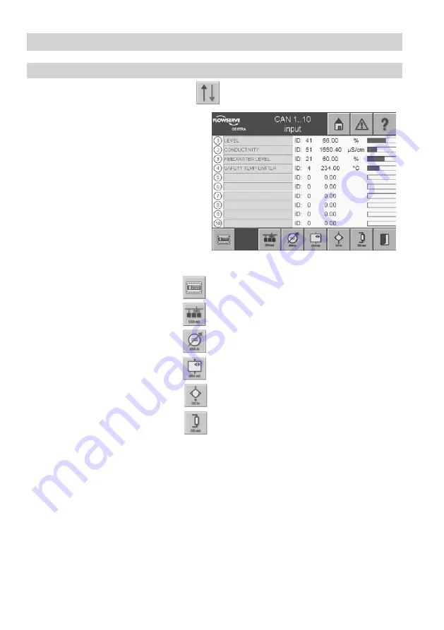
CAN 1...10 input

To adjust the inputs/outputs, press the button  

 in the menu 

Overview

.

1.  The green input fields list the names of the 

current CAN inputs. Active inputs are indi-

cated on the left by a yellow number. A node 

ID conflict is indicated by a mark at the left 

side of the ID setting. To the right of this, the 

currently measured value, the associated unit 

and the graphical representation are shown. 

Current alarms are indicated for each indi-

vidual input by a mark at the left side of the 

graphical representation.

2.  To change or set the node ID, select the 

green input field. A pulldown menu appears 

with the possible CAN participants.

  If an input is already configured, the name is 

shown in the input field. Select the input  

field to call up the corresponding menu directly.

n

  To show the control equipment, press 

n

  To call up the CAN outputs, press  


n

  To show the analogue inputs, press 

n

  To call up the analogue outputs, press 

n

  To show the digital inputs, press

n

  To call up the digital outputs, press  

Содержание SPECTORcontrol

Страница 1: ...1 SPECTORcontrol User s manual 818494 01 Control Display Operating Panel GESTRA Steam Systems EN English ...

Страница 2: ...ctory settings 11 System settings 12 CAN bus connection 13 Remote monitoring 14 Integration of third party equipment 14 Using the help function 14 SPECTORcontrol 10 Bus terminal block I O module 10 Installation Description of the browser interface 15 Description of the user interface 15 Description of the input masks 16 17 Description of buttons 17 20 Menu overview 21 User Interfaces SPECTORcontro...

Страница 3: ... 29 External collective alarm 29 Alarm Accepted equipment 27 List of Equipment CAN 1 10 input 30 CAN 1 10 input NRG 26 40 31 CAN 1 10 input NRG 26 40 Setup 31 CAN 1 10 input NRG 26 40 Calibration 32 CAN 1 10 input LRG 1x 4x 33 CAN 1 10 input LRG 1x 4x Setup 33 CAN 1 10 input LRG 1x 4x Calibration 34 CAN 1 10 input NRG 16 42 35 CAN 1 10 input NRG 16 42 Setup 35 CAN 1 10 output URZ 40a 36 CAN 1 10 o...

Страница 4: ... element continuous controller setup 59 3 element 3 position controller setup 60 3 element continous 3 position controller 61 Intermittent blowdown 62 Blowdown setup 62 Forced rinsing 63 Controller Menus Analogue 1 10 input 39 Analogue 1 10 input parameter 39 Analogue 1 10 input setup 40 Analogue 1 10 output 41 Analogue 1 10 output parameters 41 Digital inputs 42 Digital inputs first value indicat...

Страница 5: ...f representation 68 Flowrate 69 Quantity of saturated steam 69 Quantity of saturated steam 1 5 70 Flowrate 1 5 setup 71 Flowrate 1 5 parameter 71 Daily log month log 72 IO list table of data 73 Internal logical links 73 Internal logical links 1 10 setup 74 Calculations 1 5 75 Systematic malfunction analysis 77 Causes 78 System Malfunctions Glossary 79 81 Glossary ...

Страница 6: ...erning equipment and bus terminal blocks Working methods that jeopardise safety must not be used Warning The parameters for the LW and HW alarm electrodes required by law can be indicated and monitored The SPECTORcontrol cannot replace the control equipment of legally prescribed limiters such as LW low water HW high water and STL safety temperature limiters Such use is considered as improper Data ...

Страница 7: ...d through use of the Internet browser on the PC SPECTORcontrol offers the following service functions n Status indication editable n Parameter indication n Parametrisation of various CAN sensors n Trend indication datalog n Indication and monitoring of maintenance intervals n Representation of accumulated quantities n Compensation of steam quantity signals only saturated steam n Indication of the ...

Страница 8: ...erated and a flashing icon is shown on the display To establish and monitor the available parameters of CANopen devices you can either use the operat ing panel directly or remote operation via the Intranet TCP IP from a PC The configuration is menu driven Make sure that you only enter correct parameters since the CAN open devices do not perform checks regarding consistency and range of values SPEC...

Страница 9: ...f compensated flowrate signals saturated steam 5 Links Number of logical links that can be freely parametrised 12 Calculations Number of calculations x that can be freely parametrised 5 Controller Number of controllers continuous 2 position 3 position controllers 5 Number of 3 element controllers continuous 3 position controllers 1 Blowdown control Number of controllers 1 Current messages and mess...

Страница 10: ...odule Installation in accordance with the enclosed equipment specification of the bus terminal block I O module Wiring SPECTORcontrol Wiring in accordance with the enclosed equipment specification of the visual display and operating panel CPC EP or XV XXX Bus terminal block I O module Wiring in accordance with the enclosed equipment specification of the bus terminal block I O module ...

Страница 11: ...hort power supply failure of up to 10 ms will be buffered by the power supply unit In the event of a longer power failure you have to restart SPECTORcontrol in order to restore the power supply Factory settings The graphical screen masks are configured by GESTRA All adjustable masks are completely available no matter whether the indicated instruments are part of the bus system or not Subsequent ex...

Страница 12: ...automatically terminated and the password must be entered again The equipment features the following default settings n Time Real time date and clock battery backed n Contrast Contrast 50 Backlight 100 n Language English n IP address settings 192 168 0 99 n Passwords Level 1 for operating personnel Level 2 for engineering personnel Level 3 for commissioning personnel GESTRA factory setting Note Af...

Страница 13: ...TRONIC BUS CAN 2 x 2 x mm2 or RE 2YCYV fl 2 x 2 x mm2 Cable length Number of pairs and conductor size mm2 125 m 2 x 2 x 0 34 250 m 2 x 2 x 0 5 335 m 2 x 2 x 0 75 500 m available on demand depends on bus configuration 1000 m 1000 m Note The design and preparation of the data cable is an important factor for the electromag netic compatibility EMC of SPECTORcontrol Connection should therefore be carr...

Страница 14: ... administrator The IP address must be uniquely defined in the network The setting is made in the Autoexec cmd on the flash card via an FTP connection or CF card reader If this is not required this entry can be hidden You must then make sure in future that the network cable is inserted as WinCE resets the IP address You can find further information on the installation CD in Remote Maintenance or th...

Страница 15: ...ton WebEPAM To confirm the authentication that follows press OK Description of the user interface The user interface consists of three areas Note For security reasons only one logged in user can access the system via browser The direct operation of SPECTORcontrol is still possible but a simultaneous operation local and remote access should be avoided The title bar shows the company logo the title ...

Страница 16: ... changing the language country specific units e g temperature will not be changed A plausibility test is not carried out For the input mask only the indicated limited set of characters can be used Minimum and maximum values are indicated above and below the current entry Values that are not within the admissible range will not be accepted The mask is used for selecting the type of manual operation...

Страница 17: ...ed in the previous menu The selected mode of operation is indicated by the icon on the button Description of buttons Button Description Return to start menu grey no alarm activated Current alarm indication red alarm acknowledged but still activated flashing alarm activated and not acknowledged Indicate help texts for current page Go to maintenance logs Go to datalogs trends Go to quantities logs O...

Страница 18: ...Go to source origin of malfunction message Indicate alarm details Delete all history messages waste bin delete electrodes and limiters Filter the alarm history Sort the alarm history Go to the malfunction history of the burner Go to collective error alarm configuration Acknowledge apply Backspace Go to the burner menu ...

Страница 19: ...nu Indicate the 3 element controller menu Indicate blowdown Indicate multiple pump control Continuous blowdown valve forced rinsing menu Go to the I O menu Go to the menu of the control equipment Indicate the CAN inputs Indicate the CAN outputs Indicate the analogue inputs I O modules Indicate the analogue outputs I O modules ...

Страница 20: ... inputs I O modules Indicate the digital outputs I O modules Calibrate Delete Configurable logical links AND OR SR with timer Ton Toff Tpuls Configurable calculations x Indicate the configurable data table Forwards backwards in steps of 3 min in datalog Forwards backwards in steps of 10 min in datalog ...

Страница 21: ...nued Menu overview The parameters have individual setting options which are password protected Press on one of the following pages and enter your password n The titles can be given new names n The bar graphs can be assigned to CAN participants n The limiters are shown in the upper area after switching on n Six signals can be shown in the centre Select the desired type or hide the signal n To show ...

Страница 22: ... modification of the basic settings has a direct effect on the boiler monitoring system and the operation functions We recommend the following configuration sequence 1 Check configure system settings 2 Check configure connected CANopen equipment 3 Check configure connected analogue equipment I O module 4 Check configure connected digital equipment I O module 5 Check configure controller 6 Check co...

Страница 23: ... time n To change the contrast and brightness of the screen press the button Change contrast n To change the language press the Language button n To change the password press the button Change password n To change the IP address press the button Change IP Changes only take effect if there is a network cable connected n To save or restore the default plant configuration press the button Factory set...

Страница 24: ...he button Touchpanel cleaning followed by the button Start to activate the screen clean ing By doing this the control panel becomes inactive and the display can be cleaned within a timeframe of 30 seconds 5 Press the Visible buttons button to show hide program modules that are not required 6 When using a resistive touch screen an additional button Calibrate resistive touch appears in the lower ope...

Страница 25: ... the input mask The on screen keyboard can be used to overwrite or modify this text Note that a maximum of 8 characters can be entered 6 Confirm the input of the password by pressing the button Note All changes to the configuration take immediate effect IP address settings 1 Press the button Change IP in the menu System 2 The menu Change IP is password protected Press and enter your password 3 Sel...

Страница 26: ...menu System 2 The menu Bus terminals IO module is password protected Press and enter your password 3 The physical quantity of the individually inserted Wago IO channels is shown and parametrised If the number inserted is smaller than the maximum possible expansion the channels become inac tive greyed out in the relevant menu 4 Use the button Overview to jump directly to the inputs outputs to be ad...

Страница 27: ...0 Actuating drive URZ 40a Actuating drive control unit Third party companies Jumo CANtrans p Temperature sensor Jumo CANtrans T Temperature sensor Digital inputs WAGO type 750 400 24 V Digital inputs WAGO type 750 513 Floating relay contact 2A Analogue inputs WAGO type 750 466 000 200 4 20 mA WAGO type 750 476 10 V WAGO type 750 461 003 000 PT 100 1000 WAGO type 750 461 000 002 10R 1k2 Analogue ou...

Страница 28: ... press the button 1 The alarm information states the alarm number a short description of the cause and the time when the alarm was triggered eliminated and acknowledged 2 The alarm text appears over two lines Top line Name of equipment Next line s Reason for the alarm message Note The alarm details refer to the alarm marked in black in the menu Alarms ...

Страница 29: ...riggered eliminated and acknowledged the alarm number and a short description of the cause 3 To select an alarm message select the corresponding line The selection is highlighted in black 4 To delete all alarms that are no longer relevant press 5 To view further details of an alarm press The menu Alarm details appears 6 To filter alarms press The following filters are available All alarms Only act...

Страница 30: ...tation are shown Current alarms are indicated for each indi vidual input by a mark at the left side of the graphical representation 2 To change or set the node ID select the green input field A pulldown menu appears with the possible CAN participants If an input is already configured the name is shown in the input field Select the input field to call up the corresponding menu directly n To show th...

Страница 31: ...f the CAN inputs 2 If a CAN input is already parametrised a relevant status screen like this is shown in this example the capacitive level electrode NRG 26 40 3 The setup menu is password protected Press and enter your password 4 To get to the following setup menu press the button Menus of Inputs Outputs continued Note The settings for the HiHi and LoLo values can be used for alarms and the Hi and...

Страница 32: ...fill level that relates to 0 sight glass Wait until the level has stabilised and then press the button Calibr 0 This button stores the relevant raw data values 5 Now start a fill level 50 sightglass Wait until the level has stabilised Enter the fill level value in the green input field and press the button The interpolated raw data value for 100 is shown under the input field 6 Use the button Rest...

Страница 33: ...ld In the input mask the on screen keyboard can be used to enter or change the name 4 To change the range values and limit values select the relevant input field 5 In the input mask the on screen keyboard can be used to enter or change the value The elec trode delivers a measured value between 0 5 and 12 000 µS cm The range specification is only relevant for illustrating bar graphs or datalogs Not...

Страница 34: ... NORM is suitable for steam boilers operating with variable pres sure which means that the boiler does not have a fixed working pressure e g low load 10 bar full load 15 bar 7 Linear To ensure that the readings are based on 25 C set the TK value to between 1 6 and 3 0 C default is 2 1 C This setting permits the linear temperature compensation of the measured value over the whole measuring range Th...

Страница 35: ... In the input mask the on screen keyboard can be used to enter or change the name 4 To change the limit values select the rel evant input field These limit values are only for adjusting the numerical representation to the actual lengths of the four rods 5 The level electrode NRG 16 42 only works when used in water with a minimum electrical con ductivity If the electrical conductivity of the water ...

Страница 36: ...green input fields Active inputs are indicated on the left by a yellow number A node ID conflict is indicated by a mark at the left side of the ID setting To the right of this the currently measured value the asso ciated unit and the graphical representation are shown Current alarms are indicated for each individual input by a mark at the left side of the graphical representation 2 To reconfigure ...

Страница 37: ...or change the node ID select the green input field The default factory setting is 48 When using more than one URZ 40a a different node ID must be set here and in the electrode 2 Use the button Node On Off to activate or deactivate the input 3 To name the CAN input select the green input field In the input mask the on screen keyboard can be used to enter or change the name 4 To change the limit val...

Страница 38: ...e 5 Always identify the current raw value of the feedback potentiometer A status report is also shown in the area below the buttons This also contains the end position Open or Close 6 When you have moved the valve in the de sired direction and reached the end position the adjustment can be made and the raw value that has been reached at that point is written below the relevant buttons Note When yo...

Страница 39: ...he left side of the graphical representa tion 3 To configure an input select the green input field The menu Analogue 1 10 Input ap pears Analogue 1 10 input parameter 1 If an analogue input has already been parametrised a corresponding status screen as shown here is displayed In this example it is a valve position poti 2 The parameters for the analogue input are shown in the display field 3 To con...

Страница 40: ... To select or change the type of sensor press the Type button The types of input are shown in a list and can be selected individu ally The selected type must tally with the components used in the WAGO bus terminal block 4 To activate or deactivate the analogue input press the button AI On Off 5 To select the unit of the measured value select the green input field 6 Use the on screen keyboard to en...

Страница 41: ...s 1 The menu Analogue 1 10 Output is password protected Press and enter your pass word 2 To name the analogue output select the input field Name 3 In the input mask the on screen keyboard can be used to enter or change the name 4 If the analogue output is not specified by a controller you can select a signal to specify the output by pressing the button Type You have the choice of a Can input an an...

Страница 42: ... keyboard to enter or change the name in the input mask 6 Use the three level Alarm button to select whether the digital input generates an alarm message Alarm at signal value 0 OFF yellow Alarm at signal value 1 ON yellow Alarm OFF grey 7 Press the button 1st Alarm to configure the initial value messages When the function is configured the area with the symbol 1st is shown in the status screen of...

Страница 43: ...ycles e g pump s on off Menus of Inputs Outputs continued Digital inputs first value indication 1 In the menu Digital Inputs press 2 The display field shows the digital inputs with the corresponding names 3 The menu Digital Inputs is password pro tected Press and enter your password 4 Use the buttons From DI XX To DI XX to specify the range The corresponding name is shown accordingly ...

Страница 44: ...he button DO 1 20 shown on the left 7 When you press the button on the right the digital output can be interconnected with a switch point HiHi Hi Lo LoLo of the CAN input or analogue inputs limiters or with the result of a logical link if it has not been parametrised in a controller Controller outputs are dominant 8 Further information on setting up the limit values can be found in the chapter for...

Страница 45: ... malfunction the buttons or text boxes are highlighted in red 2 To show or configure the control equipment press the respective button NRS 1 40 1 To adjust the control equipment press the button NRS 1 40 or NRS 1 40 1 in the menu Current values control equipment 1 The display area shows the current param eters for the control equipment Malfunctions are shown in red 2 The menu NRS 1 40 1 is passwor...

Страница 46: ... the input mask the on screen keyboard can be used to enter or change the name Note Menus of Inputs Outputs continued NRS 1 40 41 Register limiter 1 4 1 To register or change a limiter press the rel evant button in the status menu of the NRS 1 40 1 Limiter 1 4 2 When you press the button Type a pulldown menu appears and you can select an available limiter from it 3 The node ID is automatically ass...

Страница 47: ...CTORcontrol but are implemented by the control circuit of the SPECTORcontrol LRR 1 40 setup 1 Select the menu LRR 1 40 2 To change or set the node ID select the green input field 3 In the input mask the on screen keyboard can be used to overwrite or change the value 4 The button Node On Off switches the node ID to active or inactive 5 To name the LRR 1 40 select the input field Name 6 In the input...

Страница 48: ...troller To rename the control ler select the input field 3 The current name appears in the input mask The on screen keyboard can be used to over write or modify this text 4 The controller can be enabled or disabled by a digital input Select the green input field at the bottom to go to the relevant selection menu 5 Select the signal that shall enable 1 or disable 0 the controller If no signal has b...

Страница 49: ...ld Position shows the position indicator To choose a signal to deliver the position feedback signal select the green input field All established signals are shown 10 Select the signal that is to deliver the signal Further information on setting up the devices can be found in the menus CAN input and Analogue input 11 The green input field Manip variable shows the manipulated variable element To cho...

Страница 50: ...To change the limit value select the green input field 3 The current value appears in the input mask The on screen keyboard can be used to enter or modify this text 4 To change the gradient select the green input field Note The limit value is the setpoint the actual value If the value is below this level the soft start is automatically activated and drives the setpoint to the set gradient This hap...

Страница 51: ...f the controller is highlighted in yellow Below this the current actual value is shown The setpoint is next to it and the current controller data is below it 4 To change the internal setpoint select the green input field 5 The current value appears in the input mask The on screen keyboard can be used to enter or modify this text 6 In the input field Manual a manipulated variable can be set after t...

Страница 52: ... on setting up the devices can be found in the menus CAN input and Analogue input 5 To toggle between fill and discharge control press the button Fill control or Discharge control The selected control mode is indi cated on the right 6 The bottom field specifies the actuator This is highlighted in yellow if pump and or valve control have been set 7 To set the valve control press the button Valve co...

Страница 53: ...f there are several pumps available and automatic mode is activated the pump with the shortest operating time is selected first provided it is ready for operation Pump 1 3 setup 1 Press the button Pump 1 3 in the menu Pump control 2 The established digital input signal is indi cated in the green input field Ready Select the input field to show all established inputs 3 Select the input signal that ...

Страница 54: ...s Hi and Lo are shown next to that 4 Below the status indicator Enabled Disa bled the actual value X the switchpoint maximum Hi and the switchpoint minimum Lo are represented as a graph 5 Use the arrow buttons to select Automatic mode Stop or Manual mode The type of operation that is set is shown in yellow above the arrow buttons 6 In manual mode a mask with buttons will open Use the buttons to op...

Страница 55: ...ord 3 Use the arrow buttons to select Automatic mode Stop or Manual mode The type of operation that is set is shown in yellow above the arrow buttons 4 The total run time of the pumps is shown in yellow Note If there are several pumps available and automatic mode is activated the pump with the shortest run time is started first provided it is ready for operation ...

Страница 56: ...found in the menu Analogue input 9 The relevant established signal receiver is shown in the green input field Open and Close Select the input field to show all established digital outputs 10 Select the digital output that is to be activated Further information on setting up the devices can be found in the digital outputs menu 11 The green input field Offset displays the current value To enter or c...

Страница 57: ...meters can be entered for the PID controller in the input fields P Proportional I Integral and D Differential 9 The current value appears in the input mask The on screen keyboard can be used to modify this 10 Below the status display Enabled Disabled and the controller that has been set the actual value X the setpoint W the manipulated variable Yw and the position feedback signal Yx are graphicall...

Страница 58: ...eyboard can be used to modify this 4 The controller can be enabled or disabled by a digital input Select the green input field at the bottom to go to the selection menu 5 Select the signal that is to enable 1 or dis able 0 the controller Further information on setting up the devices can be found in the menu Digital inputs If no signal has been selected the acronym NC not connected appears This mea...

Страница 59: ...ments will be indicated 9 The green input field Position shows the position indicator To choose a signal to deliver the position feedback signal select the green input field All signals that have been set may be se lected 10 The green input field Manip variableshows the manipulated variable element To choose a sig nal for the manipulated variable select the green input field All signals that have ...

Страница 60: ... an external setpoint select the green input field All established sensing ele ments will be indicated 9 The green input field Position shows the position indicator To choose a signal to deliver the position feedback signal select the green input field All signals that have been set may be se lected 10 The green input fields Open and Close show the relevant adjusted signal receiver Select the inpu...

Страница 61: ... mode the manual manipulated variable is entered into the green input field MANUAL 8 The controller parameters can be entered for the PID controller in the input fields P Proportional I Integral and D Differential 9 The current value appears in the input mask The on screen keyboard can be used to modify this 10 Below the status display Enabled Disabled and the controller that has been set the actu...

Страница 62: ...parametrisation 6 Press the button Manual to manually start the intermittent blowdown process The pulse interval time is restarted Blowdown setup 1 Press the button in the menu Intermittent blowdown 2 The green input field Signal assignment shows the name of the signal output to be activated Select the green input field to show all established signals 3 Enter the values in the fields Blowdown dura...

Страница 63: ... monitored 5 Press the button Setup to to establish the forced rinsing 6 Enter the valve run time in the field Valve run time This is calculated from Close to Open The run time is automatically doubled 7 The manipulated variable Name is automati cally produced from the connected actuator Note The button Forced rinsing only appears for a parametrised conductivity electrode LRG 16 4X for the paramet...

Страница 64: ...lations 5 computations of all parametrised measured values and con stants using basic calculating methods Boiler Menus Boiler Press the button in the menu Overview to get to the boiler data The diagram in the display field corresponds to the schematic representation of the boiler sys tem with the most important valves and sensors and the dynamic representation of the relevant measured values It ca...

Страница 65: ...he limit values are immedi ately shown by red spots 3 Select the input field to go to the setup menu Boiler Menus continued Maintenance 1 5 setup 1 Select the green input field for the desired signal in the maintenance menu 2 The menu Maintenance 1 5 setup is pass word protected Press and enter your password 3 Select the green input field to enter or change the signal assignment All digital inputs...

Страница 66: ... relevant input window to show the representation of a datalog The menu Datalog 1 5 opens Datalog 1 5 setup 1 Press the button Setup 1 5in the menu Datalogs 2 Select the input field Name to give the data log a name 3 The current name appears in the input mask The on screen keyboard can be used to modify this 4 To choose a signal select the relevant input field All measured values from the areas CA...

Страница 67: ... increments for 60 min increments to change the graduation of the time base stretch compress 4 Press the button Online to update the data The most recently stored data set is shown 5 Use to open the menu Edit datalog 1 5 Note Select any area of the display field to display a ruler The ruler can be shifted within the time base The numerical measured values shown correspond to the position of the ru...

Страница 68: ...am Press Save in the information window that opens Saved datalogs can be read out via an FTP from the CompactFlash card and can be evaluated using a spreadsheet program for example 3 Press the button to delete the current diagram Press Delete in the information window that opens Note The min max value that appears is produced from the original range limit for the meas ured value to be represented ...

Страница 69: ...turat ed steam by an amount using temperature pressure press the button Qty of steam 5 To configure a flowrate measurement press the button Flowrate 1 5 Setup 6 Select the relevant input window to show the parameters of the flowrate measurement The menu Flowrate 1 5 Parameter opens Quantity of saturated steam 1 Press in the menu Flowrate 2 The green input fields take you to the configu ration menu...

Страница 70: ...her evaluation of the measured value Press the green input field to toggle the unit between kg x and t x 6 The entries in the green input fields Range 0 and 100 are required for representation in the datalog and as bar graphs in the relevant views Quantity of saturated steam 1 5 Boiler Menus continued Note You can only select pressure or temperature for saturated steam compensation In the pulldown...

Страница 71: ...d in h per hour m per minute s per second Boiler Menus continued Flowrate 1 5 setup 1 In the menu Flowrate press the button Flowrate 1 5 Setup 2 To name the flowrate measurement select the input field Name 3 The current name appears in the input mask The on screen keyboard can be used to modify this 4 To enter the flowrate that is to be accumu lated select the green input field Signal and select t...

Страница 72: ...h Note Use is made of a circulating memory in order to save the data records This type of storage makes it possible to keep the data of the last 12 months in the month log and a complete month 31 days in the daily log If a month has less than 31 days the data record saved in the last month with 31 days marked with time indication will appear in the space for the day s that are not used e g 31st da...

Страница 73: ...ered The measured value is then shown with the following parameters left side status ON OFF current measured value in numbers current measured value as bar graph signal status 1 Press the button in the menu Boiler 2 There are 12 logical links available 3 Select a green input field to go to the setup menu for the relevant link Note The number on the left next to the name green input field shows the...

Страница 74: ...down delay time can be set in input field TP Pulse time can be set in the input field 5 Select the green input field at the input of the link Select the desired signal CAN input HiHi Hi Lo LoLo Analogue input HiHi Hi Lo LoLo Digital input parametrised dig inputs Internal log link output of a parametrised log link 6 Select the buttons on the inputs or on the output of the link symbol to determine w...

Страница 75: ...nputs outputs Steam flowrate 4 These parameters are combined with each other using the following logic modules plus minus multiply divide The interim result and final result are shown next to the logic modules 5 Press and parametrise the Calcula tion 6 Use the button On Off to activate or deactivate the calculation 7 Select the green input field to name the calculation In the input mask the on scr...

Страница 76: ...of the cal culation white background OFF yellow background ON No plausibility test is carried out between the individual parameters If HiHi LoLo alarms are switched off no entry is made in the alarm log Calculations are used in the logical links and controllers Boiler Menus continued ...

Страница 77: ...lfunction analysis System Malfunctions Step 1 start Remove terminal strips in all bus participant sensors Level electrode Conductivity electrode Pressure sensor Temperature sensor etc Step 3 Switch on power supply for the bus participants of the system for example NRS and NRG Step 2 Attach the terminal strips of the sensor for a system for example NRS and NRG electrodes System OK Remove the termin...

Страница 78: ... the set baud rate If the baud rate is incorrectly set the URB 2 emits an acoustic signal Is the baud rate the same for all equipment System malfunctions occur if CAN bus components have been incorrectly assembled or configured if the device overheats if there is interference in the supply network or if the electronic components are faulty Other systems malfunctions include n Communication errors ...

Страница 79: ...it may be necessary to repeat the intermittent blowdown pulses The intermittent blowdown pulses can be repeated up to 5 times within 5 30 seconds pulse interval Sensitivity conductivity level control The level electrode NRG 16 42 only works when used in water with a minimum electrical conductivity If the electrical conductivity of the boiler water is 10 μS cm at 25 C set the sensitivity to 0 5 μS ...

Страница 80: ...able TK Linear TK Norm or TK Auto TK Linear To ensure that the readings are based on 25 C set the TK value between 0 and 3 0 C default set ting 2 1 C This setting permits the linear temperature compensation of the measured value over the whole measuring range This method is usually applied for steam boilers operating at a constant service pressure After the TK is set and the service pressure is re...

Страница 81: ...dify the cell constant In this case change the cell constant until the reading and the indicated conductivity match 24 hour rinsing conductivity control To prevent blocking of the continuous blowdown valve a rinsing pulse is triggered when the mains voltage is switched on The continuous blowdown valve is actuated and opens for 2 minutes After this period the valve is motored into the CLOSED positi...

Страница 82: ...82 For your notes ...

Страница 83: ...83 For your notes ...

Страница 84: ...men Printed in Germany Information about representatives around the world can be found at www gestra de GESTRA AG Münchener Straße 77 28215 Bremen Germany Telefon 49 421 3503 0 Telefax 49 421 3503 393 E Mail info de gestra com Web www gestra de ...

Отзывы: