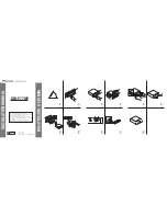
Step 1 — Complete Back Panel Connections
The order in which you connect the cables is not important. The con-
nections are discussed in the order they are numbered in figure 8,
above. Individual connectors are also shown in the margin next to each
description.
1. Power.
Connect the power cable. As soon as power is supplied to
the unit, the AP400 initializes and all front-panel LEDs and the LCD light.
The power module accommodates 100–240Vac, 50/60Hz, 30W.
2. Output A–D.
Connect up to four line-level outputs (left) to external
equipment (video CODECs, AP Telephone Interfaces, VCRs, tape
recorders) using the three-terminal Phoenix™ push-on connectors.
3. Input A–D.
Connect up to four line-level inputs (left) from external
equipment (video CODECs, AP10s, VCRs, etc.) using the three-terminal
Phoenix™ push-on connectors.
4. Output 1–4.
Connect up to four line-level outputs (left) to external
equipment using the three-terminal Phoenix™ push-on connectors.
5. Mic 1–4
Connect up to four microphones (left) using the three-ter-
minal Phoenix™ push-on connectors.
WIRING THE PHOENIX BLOCK CONNECTORS:
One three-terminal Phoenix push-on connector is provided for each
line-level input and output. Note that each position on the three-ter-
minal Phoenix™ push-on connector has three possible wiring posi-
tions: + (positive), - (negative), and
↓
(ground). Simply insert the
appropriate wire into the appropriate connector opening and tight-
en down the top screw. Once the leads are wired into the three-ter-
minal connector, insert it into the back-panel connector on the
AP400 with the set screws on top. Also note the position of the con-
nector in relation to the screened legend on the back of the unit:
overlapping from one channel to the other can cause improper
operation.
T E CH N I C A L S U P P O RT:
1.800.283.5936 (USA) OR 1.801.975.3760
I N STA L L AT I O N •
EQUIPMENT INTERCONNECTIONS
18
+
-
1
2
3
4
5
6
7
8
9
10
11 12
Figure 8. Back Panel Connections


