Section 4 • Repair Procedures
Part No. 227656
GR-20J • GR-26J
4 - 43
September 2016
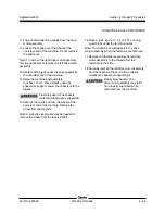
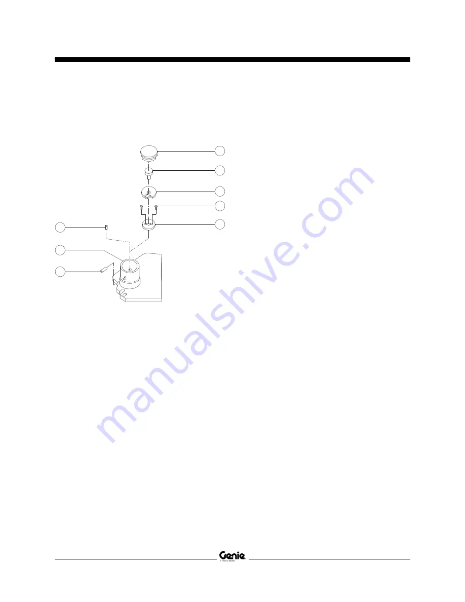
8 Using the illustration as a guide, mount the
potentiometer on to the plate and securely
tighten with the nut.
a
steer yoke pivot cap
b
potentiometer
c
potentiometer mounting plate
d
fasteners
e
bottom plate
f
sensor activator pin
g
chassis
h
screw
9 With a multimeter set to read 4K±0.2 ohms,
connect the leads to the green and black wires
of the potentiometer.
10 Adjust the potentiometer until a reading of
4K±0.2 ohms is obtained.
11 Install the bottom plate and it's fasteners on the
steer yoke pivot.
12 Install the sensor activator pin on to the steer
yoke pivot.
Note: Be sure the sensor activator pin is engaged
into the sensor.
13 Install the plate along with potentiometer on the
steer yoke pivot and securely tighten the
potentiometer stem with the screw. Do not over
tighten.
14 Install the plastic cap on to the steer yoke pivot.
15 Connect the steer angle sensor wire harness to
the machine wire harness.
16 Calibrate the steer sensor. See 1-2,
Controller
Adjustments
for
How to Calibrate the Steer
Sensor.
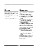
STEER AXLE COMPONENTS
f
a
b
c
d
e
h
g
Содержание GR-26J
Страница 12: ...September2016 GR 20J GR 26J Part No 227656 This page intentionally left blank ...
Страница 75: ...Section 4 Repair Procedures Part No 227656 GR 20J GR 26J 4 29 September2016 This page intentionally left blank ...
Страница 109: ...Section 6 Schematics Part No 227656 GR 20J GR 26J 6 3 September2016 ECM Pin out Legend ...
Страница 118: ...Section 6 Schematics 6 12 GR 20J GR 26J Part No 227656 September2016 This page intentionally left blank ...


