Section 3 • Scheduled Maintenance Procedures
Part No. 227656
GR-20J • GR-26J
3 - 9
September 2016
CHECKLIST
A
PROCEDURES
A-5
Replace the Hydraulic Suction
Strainer
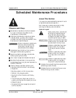
Genie specifications require that this procedure be
performed every 100 hours or monthly, whichever
comes first.
Replacement of the hydraulic suction strainer is
essential for good machine performance and
service life. A dirty or clogged suction strainer may
cause the machine to perform poorly and
continued use may cause component damage.
Extremely dirty conditions may require that the
suction strainer be replaced more often.
Beware of hot oil. Contact with hot
oil may cause severe burns.
Note: When removing a hose assembly or fitting,
the O-ring on the fitting and/or hose end must be
replaced and then torqued to specification during
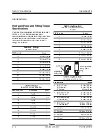
installation. Refer to Section 2,
Hydraulic Hose and
Fitting Torque Specifications.
Note: Perform this procedure with the machine in
stowed position.
1 Disconnect the battery pack from the machine.
2 Open and remove the turntable cover at the
hydraulic power unit side of the machine.
3 Working next to the hydraulic tank, remove the
fasteners securing the chassis side cover to the
chassis. Remove the side cover. Lay the side
cover and fasteners to the side.
4 Tag and disconnect the wire harness
connectors from the function manifold.
5 Tag and disconnect the cables from the motor.
6 Tag, disconnect and plug the hydraulic hoses at
the function manifold. Cap the fittings on the
manifold.
Bodily injury hazard. Spraying
hydraulic oil can penetrate and
burn skin. Loosen hydraulic
connections very slowly to allow
the oil pressure to dissipate
gradually. Do not allow oil to squirt
or spray.
7 Place a suitable container under the hydraulic
tank.
Refer to Section 2,
Specifications.
8 Locate and remove the hydraulic tank filler cap.
Set the filler cap to the side.
9 Remove the drain plug and drain all of the oil
into a suitable container.
10 Clean up any oil that may have spilled. Properly
discard the used oil.
11 Remove the fasteners securing the function
manifold to the hydraulic tank. Set the fasteners
to the side.
12 Loosen the clamp securing the hydraulic power
unit to the hydraulic tank. Do not remove the
clamp.
13 Remove the clamp securing the hydraulic
power unit to the chassis. Set the clamp to the
side.
14 Carefully remove the hydraulic power unit from
the tank and place it on a clean work bench.
Note: If necessary, loosen the bottom connector of
auxiliary pump to more easily remove the hydraulic
power unit.
15 Remove the suction strainer from the end of the
plastic tube.
16 Install the new suction strainer at the end of the
plastic tube.
Содержание GR-26J
Страница 12: ...September2016 GR 20J GR 26J Part No 227656 This page intentionally left blank ...
Страница 75: ...Section 4 Repair Procedures Part No 227656 GR 20J GR 26J 4 29 September2016 This page intentionally left blank ...
Страница 109: ...Section 6 Schematics Part No 227656 GR 20J GR 26J 6 3 September2016 ECM Pin out Legend ...
Страница 118: ...Section 6 Schematics 6 12 GR 20J GR 26J Part No 227656 September2016 This page intentionally left blank ...

