27
Model FL4000H
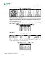
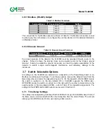
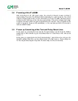
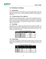
The following procedure should be used in conjunction with Figure 15:
1. Loosen the captive screws (A) located on the Optical Housing Assy.
2. Pull the Optical Housing Assy from the Base Housing Assy to separate, gently rock from
side to side if necessary to loosen the connector's grip.
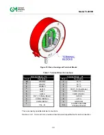
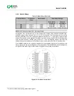
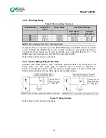
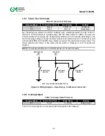
3. Make all necessary wiring connections as described in Sections 3.6.1 thru 3.6.12. For an
example of wiring, please refer to the connection diagram in Figure 5.
4. Set switch selectable options as described in Section 3.7 .
5. Reassemble the unit using steps 1 thru 2 in reverse.
CAUTION:
Do not unscrew the field wiring board from the base housing assembly for wiring.
3.5 Detector Mounting and Installation
The FL4000H is enclosed in an explosion proof assembly, which is rated for use in the
environments specified in Section 8.3.2.
The unit should be mounted free from shock and vibration and convenient for visual
inspection and cleaning.
The detector(s) should be tilted downward so that dust or moisture does not
accumulate on the sapphire window.
The detector(s) should be mounted in locations, which will inhibit people or objects
from obscuring the detector’s FOV.
NOTE
: Frequent inspection, cleaning, and sensitivity checking is suggested for detectors
mounted in dirty environments.
CAUTION:
General Monitors requires that the FL4000H conduit entry be sealed per the
Canadian Electrical Code Handbook (Part 1, Section 18-154) and NEC Article
501. Conduit seals or approved Ex d glands prevent water or gas from entering
the detector’s housing through the conduit entry. Water entering the housing
through the conduit entry will damage the electronics and nullify the warranty.
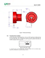
The FL4000H is mounted as shown in Figure 16 and the overall product dimensions are
depicted in Figure 17.
NOTE
: Conduit seal must be within 18” of unit.
NOTE
: Non-hardening thread sealant should be used if the plugs are removed or re-installed
in order to preserve ingress protection rating.
Содержание FL4000H
Страница 2: ...ii Model FL4000H This page intentionally left blank ...
Страница 8: ...viii Model FL4000H Figure 2 Mounting Instruction Figure 3 Wall Mounting Assembly ...
Страница 28: ...28 Model FL4000H Figure 16 Detector Mounting and Installation ...
Страница 61: ...61 Model FL4000H 6 2 Final Assembly Figure 26 FL4000H Cross Section View ...

